SimpleFOC Starter Board Dev Kit R&D

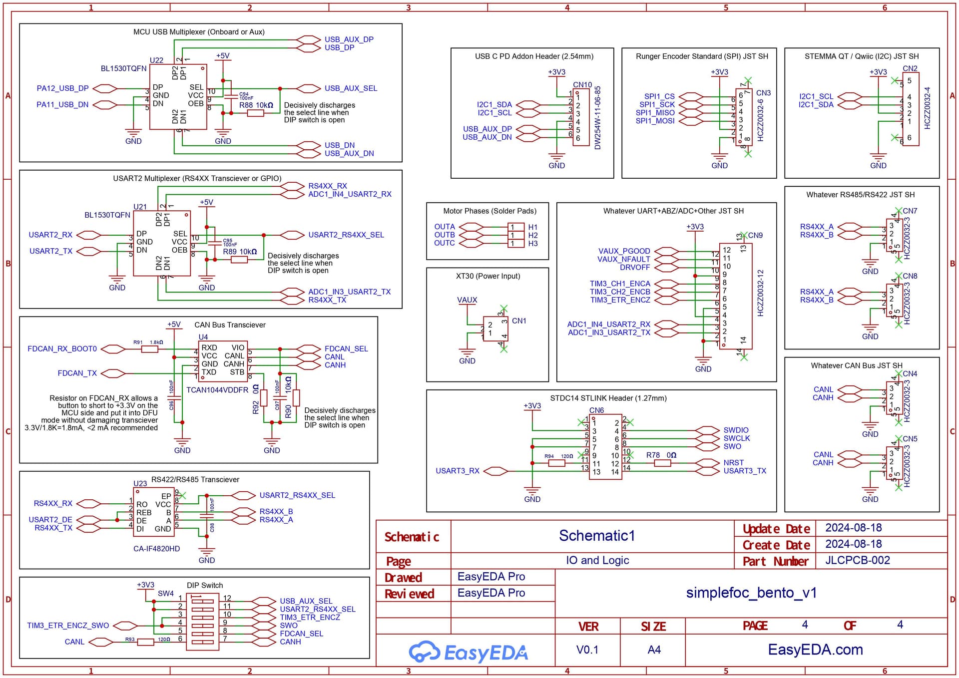
You’re right, I did not check the datasheet of the CAN Transceiver - the RXD pull-up would indeed be an issue. That’s a bummer, I think then you would need an additional component like a buffer with active low EN function so that you could switch off the connection between transceiver and MCU completely. The CAN-STB signal would then switch both the transceiver and the buffer to disable CAN and the connection at the same time.

Fair enough… there has even been a SimpleFOC dynamixel implementation which you can find in the forum…
Personally I’m just not a big fan of RS485 compared to CAN or ethernet/WiFi/BT. But that’s just my bias, probably.

Ok, makes sense, and the LPUARTs are in the PinMaps, so they should work. It makes me a bit nervous because some of the other LP-peripherals aren’t supported in Arduino.

Personally, I much prefer SWD for programming the STM32s. STLink V3s are faster at programming than other options, in my experience, and it always works without having to reboot while holding BOOT0.
The STLink VCP serial connection remains active even when the MCU reboots, so the serial console is much more useable and you don’t always miss the boot messages due to serial reconnects. Debugging is directly supported on the same connection.
Its just the most convenient way to work with these chips, I find. But of course you do have to invest in a ST-Link. But compared to all the other vendors, ST-Micro is super-fair with their programmers pricing. I think they’re even selling them below cost.

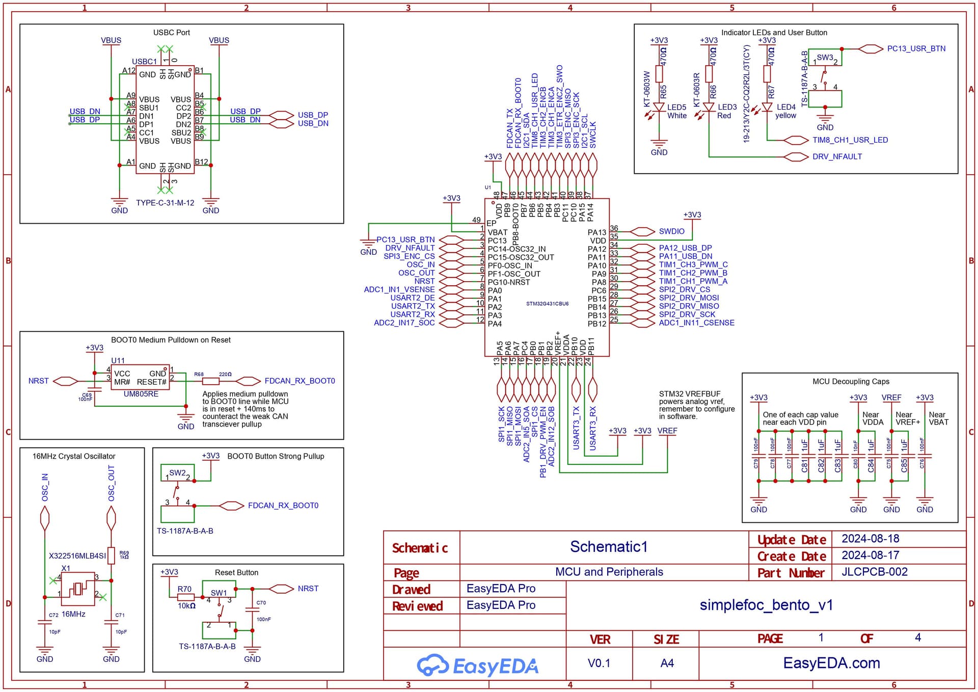
That’s a good question. After many iterations I now do it like this: I connect 3.3V via a solder (or header) jumper, normally closed. This way you can directly use it to connect I2C target devices like sensors or IMUs, and they’ll be powered with 3.3V.
If on the other hand you want to use the I2C port in target device mode, to control the driver from your RPi for example, then you cut the the 3.3V connection so as not to back-power the RPi.
Personally I never use 5V really, and there are plenty of 3.3V devices available. But should people need 5V there are StemmaQT compatible level shifters they can just plug in-between.

Ok, I get it now. It’s what I meant by saying you could not use them at the same time, but multiplexing them in this way should work fine. It will be a bit involved in terms of the code compared to having an extra pin free though :smiley:

I think it will be possible, but the result for the user will depend a lot not just on the driver board and its firmware, but also where it gets plugged into. MacBooks won’t recognize it as an approved device, and won’t give it more than 7.5W and 5V. Plugging it to a notebook PSU will give it enough juice, but then it won’t be possible to use the DFU. Probably users with a powerful USB-PD Hub will have the best experience.

1 Like

Well, I spent a while thinking about this project, and came up with a couple of realizations:
Generally this design should prioritize user friendliness over the other aspects, as the target audience is new users. With that in mind, the path forward became clear, and here is the next big revision of the schematic.


Changes are as follows:

  • High Level:
    • Moved from 6PWM to 3PWM+Enable on DRV8316C to free up a couple of pins:
      • User button is now separate from the User LED
      • User facing dedicated SPI port now has a dedicated CS pin
    • Debug header has dedicated USART and optional SWO line (for trace viewer functionality)
      • RS4XX transciever moved to become option on user facing USART port
    • Removed HUSB238 USB C PD trigger IC and associated efuse
      • The HUSB238 will be constructed into a separate addon module that plugs into the XT30 and a header with I2C and USB on it
      • This addon will use the remaining onboard efuse for protection
    • Adjusted onboard USB C connector power path to only power logic
      • Changed analog voltage reference source to STM32 VREFBUF 2.9V output, so that analog readings can still be taken even on just USB power
      • DRV8316C buck regulator output placed behind ideal diode before going to +5V rail
        • Ideal diode allows for minimal voltage drop because buck always initializes in 3.3V mode
      • VBUS placed behind B16WS Schottky diode before going to +5V rail
    • Red LED is now NFAULT
    • Added white LED to indicate system power
    • USB now has a BL1530TQFN 2:1 multiplexer IC to direct the signals between either the main USB connector or the aux USB header
    • USART2 RX and TX now have a BL1530TQFN 2:1 multiplexer IC to direct the signals between either the RS4XX transciever or a connector for UART/ADC directly
    • Added 6 pole DIP switch for configuration
      • 1: MCU USB connected to AUX header when ON, otherwise connected to onboard USB C connector
      • 2: USART2 lines connected to RS4XX transciever when ON, otherwise exposed on GPIO header and transciever unpowered
      • 3: PB3 exposed on ABZ encoder header as index pulse when ON, otherwise disconnected (mutually exclusive with 4)
      • 4: PB3 exposed on debug header as SWO output when ON, otherwise disconnected (mutually exclusive with 3)
      • 5: CAN transciever powered when ON, otherwise unpowered
      • 6: 120 Ohm termination resistor on CAN line enabled when ON, otherwise disabled
  • Pin Specific:
    • ADC1_IN2_CSENSE moved from PA1 to ADC1_IN11_CSENSE on PB12
    • PA1 now dedicated to USART2_DE
    • USART2/ADC1 lines (PA2, PA3) will now be connected to the RS4XX transciever through a multiplexer IC to switch between RS4XX, and UART/Analog-in
    • LPUART1 (PB10, PB11) changed to USART3, DE pin removed. This will be the dedicated serial port for SWD
    • PC13, PB0, and PB1 (TIM1_CH1N, TIM1_CH2N, TIM1_CH3N) PWM Low Side outputs to DRV8316C removed
    • PC13 is now USER_BTN, which has been separated from the USER_LED pin
    • PB0 is now the SPI1_CS line for the user SPI port
    • PB1 is now the PWM Enable output to the DRV8316C

This changed several of the features in the original list:

  • USB C PD no longer available on this board
  • DRV now in 3PWM mode (should be fine for almost all use-cases)
  • Dedicated UART now shared with RS4XX transceiver

I tossed all the components onto a 50x50mm square board to get a quote, and it ended up looking like this (note none of the component positions are final, and it will likely utilize the reverse side quite a bit)

4 Likes

Overall I feel quite good about this board, though after adding the connectors and some other bits and bobs, the price for 20x boards with double sided PCBA is now about $25 per board. Surprisingly enough, 100x boards is under $14 per board and I think this will work fine once the functionality is all validated.

The main feedback I would like to ask for at this stage is the following:

  • Do the connector pinouts make sense? Especially the CAN bus, RS4XX, and CN9
  • Any last concerns before I start layout (for real this time I promise :grin:)
3 Likes

Nice design! I am planning to design a similar boards using the same ICs (STM32G431 & DRV8316). This STM32 is new for me; I have used ESP32s and RP2040 before.
I have a few doubts regarding your design:

  1. Is it necessary to have a 10k pullup resistor for the NRST pin? The IC has internal pullup of 25k-55k.

  2. If the Vio pin of the CAN transceiver is connected to the MCU with 100K pull-down, Will it solve the boot conflict with the PB8 pin? The RXD will be high impedance state at boot.


    You made a clever choice with Reset IC (UM805RE) since you have used all MCU pins.

1 Like

Hello, thanks for taking a look!

  1. I think the reason for the 10k pullup is this forum post. I am pretty sure it doesn’t hurt anything to have it there and worst case scenario it could be made into a DNP component for later revisions, but allocating a spot for the footprint is worth it in my opinion.
  2. I think this is a good solution, but would suggest including a decoupling cap on the VIO line as well, and depending how big the cap is may need to reduce the resistor value a little bit. Should work fine if you have the pin available.

Really appreciate the complements, and good luck with your board!

2 Likes

I will go with your advice NRST pullup just to be safe.

@runger initially suggested disabling the CAN ic to prevent conflict with the BOOT0. I figured VIO also disables the IC without any problems with the RXD.

Thanks for your insights, I will share my schematic also.

1 Like

I can confirm that NRST pullup is safer. I made a chance discovery on my Lepton Deku Mod that if I connect a wire to the reset pin, I can trip it capacitively by touching the wire insulation and the motor at the same time with one hand. No conductive contact, and not touching the wire to the motor. Just holding it in my fingers and touching any other part of my hand to the motor. It’s actually quite convenient :stuck_out_tongue: As far as I know it’s never tripped by accident.

3 Likes

2 posts were split to a new topic: DRV8316 + STM32G431 design request for comments

Sorry for the long delay, but v1.0 layout and routing is done. Not my best work but validating the functionality sooner rather than later is more important than perfection, so I will be ordering 5x from JLCPCB today.


There shouldn’t be any functional changes since the last update, but I picked a very ambitious 40x40mm form factor that made it necessary to move to a 6-layer board. This comes with free filled and capped vias, which are also necessary for a few of the difficult part placement situations, and luckily the pricing increase is pretty minimal.

This first 5x order comes out to ~$55 per board, but I also had 50x quantity quoted which reduced to $18 per board.
Feel free to roast the board design here: simplefoc_bento_v1 - Platform for creating and sharing projects - OSHWLab

7 Likes

Boards have arrived, and they look very good! I have gotten as far as trying the Blinky project, but in the next couple of weeks my goal is to conduct a thorough board bringup process that validates as many of the individual features as possible. The next steps will be to start putting together documentation, and writing starter firmware that shows how to initialize all of the peripherals.

9 Likes

Some progress has been made on board bringup, and so far everything looks quite good! I am using this repo as the development environment for testing the board, and it is currently just a single platformio project inside. Note that this is very likely to change as I build more tooling to support the testing.

To start with there is a thorough test of the power rails under a variety of situations available here; Everything worked as expected except for the reverse polarity protection. I have been in touch with the chip vendor, and they say that the IC is not designed to protect against reverse polarity (even though their datasheet clearly shows how to implement it :roll_eyes:). Most likely I will just add the classic PFET RPP circuit and call it good.

After that, I spent some time writing an example application that exercises all onboard peripherals that can be tested standalone, which is the main contents of the platformio project mentioned above. Overall the performance seems very good, but here is a list of issues that have come up so far:

  • White power LED is way too bright

  • Yellow user LED needs to be activated by GPIO sourcing current instead of sinking, the active low configuration is confusing

  • CAN/RS4XX connector too close to 1.27mm header pin

  • AUX GPIO connector too close to USB C connector

  • The use of the MCU’s internal VREFBUF analog reference regulator requires extra setup and is not super straightforward, may consider just using filtered +3V3 rail instead

  • If board is powered from USB and XT30 and the DRV8316C buck is configured to 5V, and then XT30 power is removed, there is ~5V on the VMOT rail after. This is most likely due to the ideal diode IC behaving in a less than ideal fashion, because TI forums report that it requires substantial reverse current before it will turn off. Need to investigate a solution, but will likely either add a slight load, or just replace the IC with a low forward voltage diode.

  • The stm32duino core does not allow for an SPI peripheral to be defined without both a MOSI and MISO pin, but the MOSI pin for the MT6701 is allocated elsewhere. In the meantime I have written a custom SPI peripheral + sensor driver that works, but it’s not very elegant, so I am open to better suggestions.

  • Platformio gives mysterious “error” after successful DFU upload (if anyone knows how to fix this please let me know, I have not found anything that worked on google):

    Download done.
    File downloaded successfully
    Submitting leave request...
    Error during download get_status
    *** [upload] Error 74
    

The only other annoyance was that even though the STM32G4 MCU has a built-in DFU bootloader, platformio does not have the fairly common “1200 baud touch” method of triggering DFU mode over software. To fix this, I wrote a utility function that installs a listener for the DFU trigger in the firmware, as well as a custom script that platformio executes right before upload to send the trigger. This worked great once, but the STM32 was failing to properly exit DFU mode automatically after the update and required a physical reset, so I wrote a cursed patch that uses persistent ram to force a single extra software reset after each power on. This entire system is pretty fragile right now, but it seems to work quite well.

If anyone has any ideas for how to improve the firmware upload system, please let me know. A huge goal for this board is to make the user experience as frictionless as possible, and that means one-click uploads without having to buy a separate programmer are a must, and as you can probably tell I am willing to devote substantial effort to making this happen.

Regardless of all that, it was still possible to implement position control using current sensing for torque control. The board is powering a GIM4305 actuator module sweeping through a 45 degree angle at 2Hz (though it can go a fair bit faster :grin:


Next steps are to validate all of the communication peripherals, and then send out one more board revision to be fabricated to fix the several outstanding issues with this revision. In parallel I am beginning to work on setting up the infrastructure for writing documentation, as most of that will probably not change between now and whenever the production-ready revision is complete.

5 Likes

Man @nanoparticle this is amazing! Can’t wait to hear the updates shortly :slight_smile: looks like the new odrive micro haha

2 Likes

This looks great, exactly what I’m looking for! Can’t wait to get my hands on some.

1 Like