At this point I have helped staff a SimpleFOC exhibit in two Open Sauce conventions and one Maker Faire, and by far the most common question people ask us is “what kind of hardware should I buy to just mess around and get started with this project?” Right now the answer is kind of difficult, as it involves directing people to purchase the SimpleFOC shield from a seller on Aliexpress, then to pick one of the many Uno form-factor Arduino compatible boards (but please avoid the Atmega328), and finally grab an encoder breakout board (as long as it isn’t the AS5600). I could see that this was too nebulous and involved to really click with a lot of people, especially those who are just checking out brushless motors and have not yet developed a very strong interest. This is why I think it is time to create a definitive all-in-one starter board and dev kit, so that new users can have a super easy and smooth onboarding experience.
Several key goals have guided my development so far:
Provide as many IO options as possible, and be plug-and-play ready for a wide variety of fairly common hobbyist level projects, with no extra required accessories
The price should be very affordable, so even those who are just curious would not be opposed to buying the board
The components used should represent a high level of performance that fully shows the potential of the SimpleFOC library, i.e. no 8 bit MCu or I2C encoder
I have just finished a rough draft of schematics for a board that could potentially meet this demand, and would like to ask for comments and feedback, as well as help with naming the board .
Very good initiative!!! Providing an integrated hardware solution makes it possible to develop a sketch that with minimal modifications makes it possible to move amotor, thus allowing anyone without much effort or prior knowledge to get involved in the project
I can’t comment on the schematics, just have some general remarks:
Your design goals aren’t clear:
you want to keep it cheap to trigger most newbies interest
you want to make it a fully equipped board with lots of IO-options (CAN + RS485 + extra ports)
Both points are concuring each other.
Why not add an upgrade socket for those extra IO options? Users can decide which (if any) IO PCB they want. They might ask for WiFi or blutooth…
IMHO a starter kit would include a suitable motor and a power supply. Would it then be necessary to have these e-fuses? Aren’t there cheaper solutions? Polyfuse maybe?
Another selling point could be to offer a complete build-project (like the famous inverse pendulum), but that would require two drivers/motors.
Last not least: such an endeavour would require a worldwide dealer network and tons of money to invest.
Ok you make some very good points, I appreciate it a lot. To start off, the design goals do contradict each other somewhat, and my solution strives to find an optimal balance between them. I see a lot of value in providing a single design that does an ok job at almost everything, which makes me want to integrate as many peripherals onboard as possible. In my opinion a new user will not be super likely to know exactly which communication protocol they will need when ordering the board, and having to purchase extra accessories later adds a lot of friction.
You bring up WiFi/Bluetooth, and I did spend a lot of time thinking about how it might work in this project, but ultimately decided that by the time a new user is interested in using wireless they are probably ready to move onto a board like the Dagor driver or similar.
Starter kit might not have been the right words to use, because you’re right it does imply that a motor and power supply are provided. You’ve given me an interesting idea of including a DC barrel jack and cheap switching power supply, but I’m unsure about also providing a motor, because choosing a specific motor can be very restrictive to the kind of projects it can be used in.
I do however see this board as a stepping stone to reach the goal of providing a ready to build project, but I’m not aiming to get there right now.
With regards to price, I got a quote for double sided standard jlcpcb assembly of 20x board for $25 each, so yes it is a little more expensive than my target of <$15, but might be possible to reach $20 with some volume and slight changes to components.
You are entirely correct that this sort of effort requires substantial commitment to manufacturing and supply chain, and I am willing to invest out of pocket to set this up. I am inspired by @Karl_Makes_Music’s smart knob project and web store, it appears to be feasible to kick off if quite a bit of effort.
I’d rather an XT30 over a DC barrel jack, then I can plug a LiPo right in and have it do something, or make a barrel jack to XT30 adapter cable.
My experiences with normal (large) DC supplies is that they will work, but it’s easy to accidentally put them into a shutdown/protection mode if the motor ends up braking some inertia.
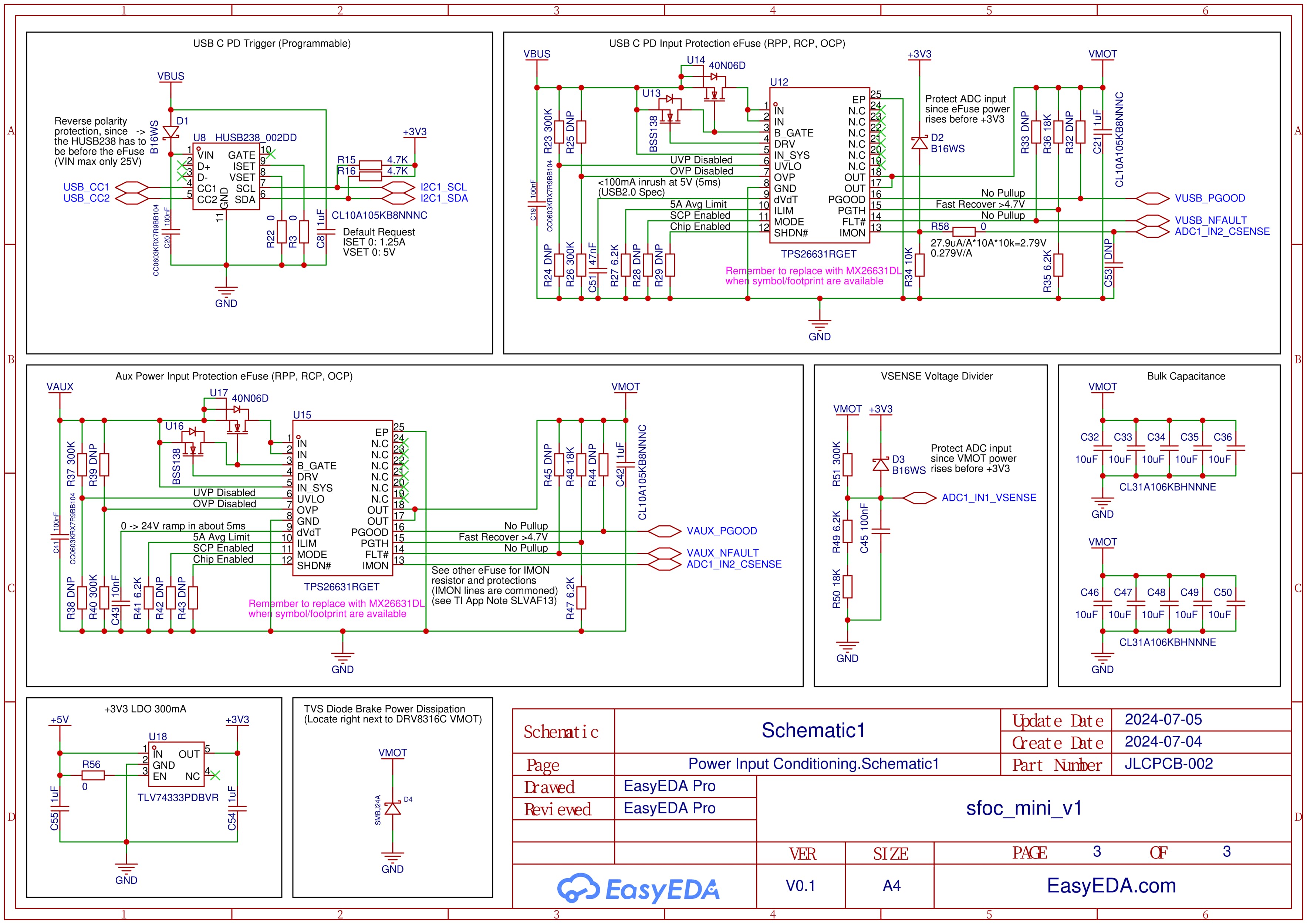
XT30 makes a lot of sense, but also the eFuse provides reverse current protection so a voltage increase should stay entirely within the bulk capacitance on the board, and get clipped if necessary by the large TVS diode. Spent a lot of time thinking about the most universally usable power architecture, and my conclusion was to just avoid backfeeding the PSU entirely if possible, as this allows support for the widest variety of power supply types.
In your opening thread you mentioned: the hurdles “shopping here and there” and searching for matching components are too high for many users, and I agree.
That’s why offering a PSU+controller+motor(s) kit is the best way out of this dilemma.
It also reduces design costs, because you won’t have reverse polarity or overcurrent scenarios.
Regarding the IO control port, the basic port should be serial_over USB to keep it within the arduino universe.
Same for the development platform. It should be 100% arduino comaptible. No platformio
, if you want to attract new simpleFOC users
I do understand your point, but really am not sure what motor to include that would be a good fit for most people’s projects. Just choosing between low resistance and high resistance motors already disqualifies one half of the projects. What motor would you suggest in this case?
I am on the fence about the power supply issue, because in my opinion looking through a spare parts bin for an old laptop power supply (~19V >2A, perfect) is not nearly the same magnitude of problem as being told to go pick an encoder from the vast array of options on the internet. If someone is getting interested in brushless motors, I feel like they can probably manage the power supply on their own.
For IO protocols, you are correct that serial over USB is the best choice for initial exploration and familiarization. But after that, I want the board to have additional capacity to grow with the user, and eventually even be integrated into their projects. Imagine someone finds SimpleFOC after looking for a way to add a motor to their existing arduino project, they would probably want a microcontroller friendly communication bus like serial or CAN.
From what I understand, there isn’t anything that can make a board specifically only PlatformIO compatible, but I’ve also never used it so maybe someone can correct me here. Not to worry though because Arduino IDE STM32 support is very good so it should work just fine.
USB-PD support means they can pick any USB-PD charger.
I already own one and I wouldn’t want to be forced to buy another one.
Most of the devices are delivered without a charger now.
Or are we talking about a PSU with CV/CC/overcurrent protection ?
I’m watching very carefully but hesitate to give my input, since I may be biased. I always go for absolute bare bone cheapest solution . You are not sending a man to Mars.
Just get something really cheap and easy to replace. This is a 90/10 solution, you can get 90% of the education with 10% of the effort.
Very interesting, it seems like the issue that @o_lampe is bringing up already has an off the shelf solution that most likely even supports SimpleFOC, and I’m not convinced our own take on this would be that much cheaper.
In my opinion, the end goal here is to make something that really addresses the problems that new users face when taking a look at this library for the first time, so I’m basing my efforts on all the different conversations that came up at the different conventions (maybe @David_Gonzalez might have some thoughts here as well). After the most common “What is FOC?”, many of the questions were pertaining to driver boards and the associated electronics, and what combination of MCU, power stage, and feedback hardware was compatible or sufficient for a certain use-case. Substantially less people had questions about the motors, and I don’t recall getting a single question about power supplies, which is what really informed my project direction here.
For getting something spinning in as little time as possible, @Valentine’s suggestion of bundling the cheapest functional motor seems like the best path forward.
The USB C PD input has an unfortunate problem that unless you have a way to combine high wattage PD and data on the same cable, then you would need to constantly switch between plugging in the computer and the power supply during the development cycle, which also prevents the user from having an easy serial connection while the motor is running (a pretty critical feature). Eventually I am relying on @VIPQualityPost’s PD injector project to provide a solution, but this does now require an extra accessory. It’s probably a niche enough application that people who really want to use PD can just get the extra board though. There is still the option of splitting power and data onto two separate USB C ports to provide a short term solution, but then it won’t be compatible with a PD injector.
Thanks for the feedback so far!
I will start moving forward with this project again, but please continue sending comments when you think of them. Next steps are to do some last minute component optimizations for a little bit of cost savings, and then beginning the board layout. With that in mind I have a few more important questions to ask the community:
What is the most accessible way to expose IO on the board? The most basic solution that I am leaning toward is to have standard 2.54mm pin header holes, and then include some headers that the user can solder on. We can also go as fancy as using SMD right-angle JST connectors and then include some connector pigtail cable assemblies, but this would probably raise the price way too much.
What is the most universal mounting solution? My guess is a square with M3 clearance holes in the corners, and then if anyone needs a different spacing they will need to get an adapter. Would love to see if anyone can come up with a better option though. Whichever solution we choose should fit the included motor, so it would be a good idea to start looking around for a good motor candidate at this stage (open to suggestions, maybe the classic 5010-360kv would be decent and reasonably priced in bulk).
Another thing that is worth pointing out is that this design is meant to be the “fully loaded” version, because in my experience it is always easier to start with all of the functionality and remove some of it, than to add more functionality after the design is already mostly finished. This means if we find out people are not using several features, we can design a “light” version that has exactly what people are looking for.
Does anyone know the winding resistance of them?
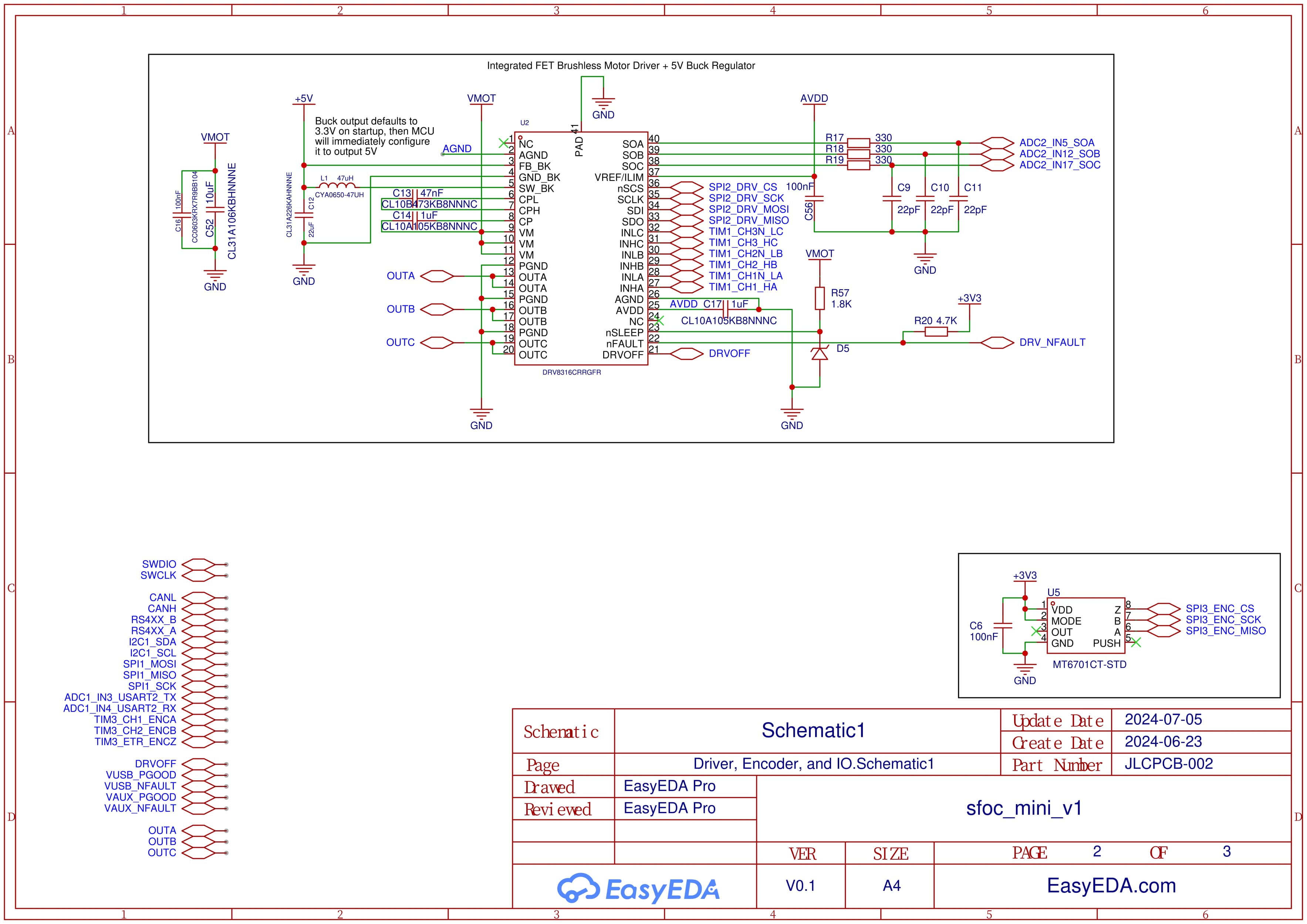
I’ve seen datasheets where this motor draws +10A, while the DRV8316 is spec’d 8A peak.
It would also require a much stronger PSU than a regular laptop-PSU.
These drone motors rely on good cooling and their winding is quite hot.
Not a good candidate for desktop experiments IMHO.
I’d pick a motor with 5-10ohm winding.
Gimbal motors are expensive, but they are better suited for experiments.
Instead of providing a motor with the kit, you could suggest suitable motors by those infamous affiliate links . You’d make money without having to hold them in stock.
(I hate myself for proposing this)
Low resistance motors do take a little bit more effort to configure, but with reasonable software limits set they are perfectly compatible with lower current drives. Then once the motor is controlled in closed loop mode it becomes just as usable as a gimbal motor. This thread has some concrete numbers that look pretty good.
That is what i would use for less experienced users. If you place them on the side of the board everybody can choose from a wide range of connector types, 90 degree, upright, soldered from the bottom or the top, male, female… plus, those headers and connectors are cheap and who cannot solder these should better not start the project.
I promised I’d take a look during the holidays, so here is my take:
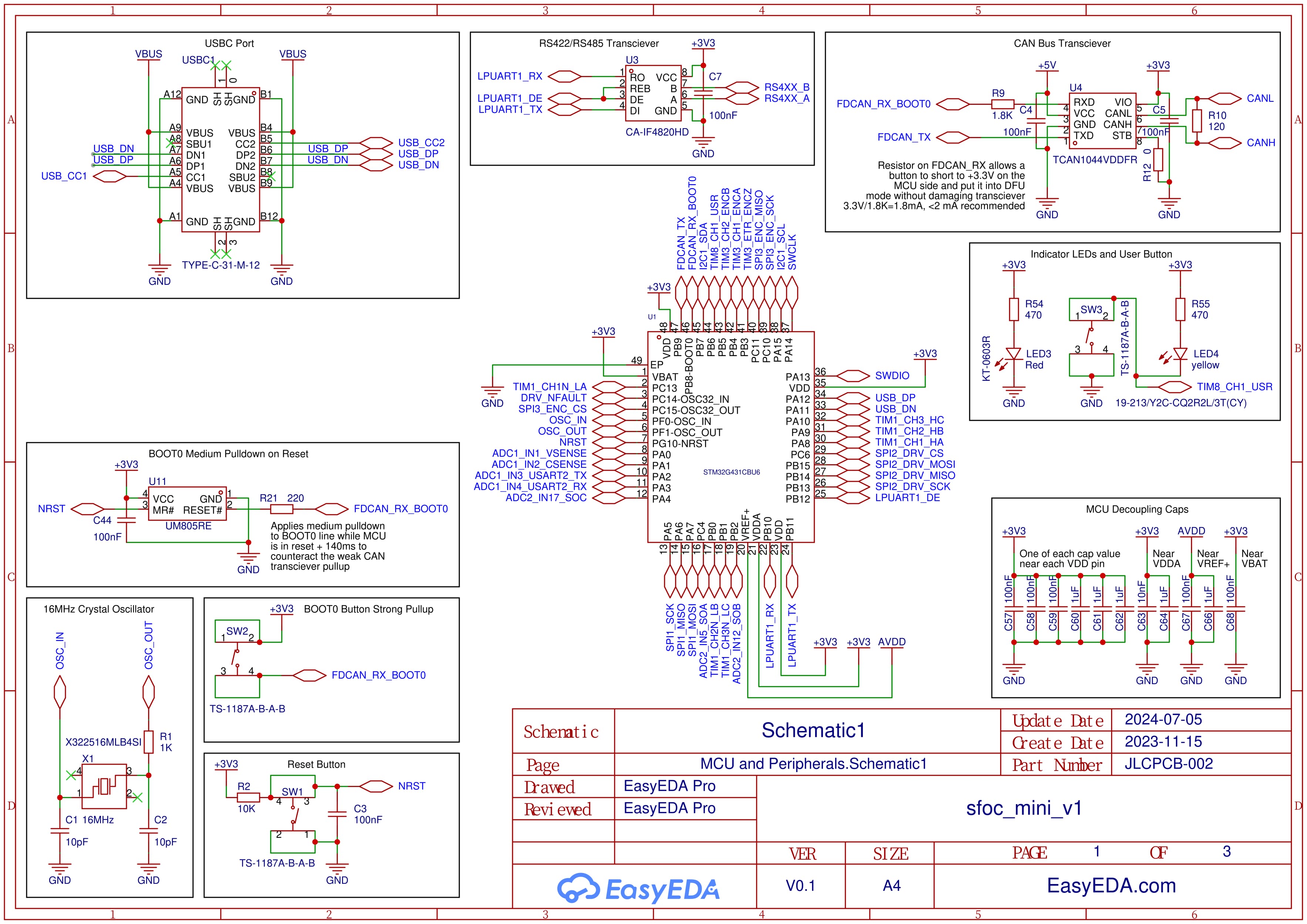
CAN Transceiver - I like the inclusion of a CAN transceiver for local comms, it would fit my world view. Given you have a model with STB input, I would wire this input to the MCU, and pull it high by default. This will save power for all the users who aren’t using it, and eliminate any conflict with BOOT0 until after the MCU powers on and switches CAN on.
The termination resistor is non-optional? Is the idea that users de-solder it if they don’t want it? I would prefer to include a solder jumper (default closed) which the user can cut if they don’t want it, or even a 2.54mm 2 pin header for bridging with a header jumper. IMHO that’s easier to use than expecting users to desolder SMD components.
RS485. I know you want a full featured board, but how common is RS485 effectively? I wouldn’t encourage its use really, so I’d be inclined to leave this off. And is there a reason to use the LPUART? It seems PB10/PB11 would also support USART3 (albeit with RX and TX reversed compared to the LPUART).
Power supplies - it looks like it will work but I’m not a fan of USB-PD to power the motor. I’d generally design it so PD powers the digital section, so you can run the MCU, program and take measurements, but not the power stage for the motor.
Even a small motor - when stalled - will be able to draw more current than many PD sources can supply. Other times the user may plug into a source that can’t supply the desired voltage, or into a non-PD USB port. So many combinations of situations can occur where the desired voltage and current aren’t available, and the same board and motor can sometimes work and sometimes not work depending on the USB port they are plugged into. That will confuse a lot of users and cause much support effort, I dare predict.
Regarding ports/headers:
For SWD programming I recommend the standard 1.27mm pitch ARM-14 header, which directly matches the small cable of the ST-Link V3. It carries SWDIO, SWDCLK, nRST, Target_VDD, and GND, and optionally also RX/TX of a serial connection (which I’d very much recommend connecting!)
For I2C I would use a JST-SH 1.0 port in “Stemma/QT” format. This would make the device compatible with the standard I2C ports widely used by Adafruit, Sparkfun and others.
For SPI I would use a JST-SH 1.0 6-pin port compatible with the sensor boards I make.
For your LEDs, it looks like you have a red power LED, and also a yellow LED shared with the user button? The way I read that you could not use the button and the LED at the same time? Also since they cost next to nothing, why not add one on the nFAULT line? I find that very convenient personally.
Could you explain a bit more about how the standby mode would work with the BOOT0 pin? It looks to me like standby mode drives the RXD pin high by default which would force the MCU into DFU mode every time. In terms of power, it looks like pulling TX high puts the driver into a recessive mode that draws 4.5mA, which granted is 2 orders of magnitude more than the standby mode, but until I get another pin free this will have to be good enough. For the termination resistor I definitely forgot to consider avoiding the necessity for SMD soldering, whoops . I will make sure to add a solder jumper for both of these things at the very least.
My case for RS485 is that when I look at existing integrated brushless servo options in the hobbyist price range (i.e. LKMTech, Steadywin, etc.), the two predominant communication protocols are CAN bus and RS485. Additionally many hobbyist serial bus servos implement a Dynamixel style protocol, which is built on top of RS485, so there could be a substantial user base that is already familiar with and would prefer to use this option. To be fair I did not verify this in conversation with the actual new users, so it could definitely be an inaccurate assumption. Finally for more advanced users, RS485 provides a plug-and-play physical layer with incredible bandwidth at up to 20 Mbps for multiple devices, which makes for a super high performance multi-axis communication solution. The reason for using the LPUART is that RS485 requires the DE pin, and after a huge amount of pin shuffling this was the only UART peripheral with that pin conveniently free.
USB PD is definitely one of the more complicated parts of the system, and I agree that it has a lot of potential to cause confusion for the users. I really want it to work, but if it’s not looking feasible then I’ll just delete the PD circuitry and move forward using USB to power only the logic as you suggest. Making it work does heavily lean on having a very robust boilerplate firmware implementation that includes a bunch of intelligent logic for dealing with every possible combination of power supply situations. One part of this would be sampling the IMON input from the eFuses at a relatively high frequency, and if it exceeds the negotiated current from the PD source then the firmware can take measures to either adjust the current draw or shut down for safety. Obviously this is a lot of work, but in my opinion it will be worth it to establish a bulletproof starter platform.
SWD - Using such a standard header makes a lot of sense, though considering that the MCU has USB DFU and COM port, the only substantial use-case I can think of is for variable viewer mode in STMViewer. What else might people be using SWD for? Let me think about the pin allocation a bit more to see if there is a way to route a USART to this header. Also having a hard time finding a good part in the JLC parts catalog that also has the keying shroud, so not sure if I’ll be able to populate this connector.
I2C - perfect, only got one question, is it better to expose 3.3V or 5V on the V+ line?
SPI - looks good, there is just one problem stemming from a lack of pin availability: The CS pin currently has to be taken from one of the other user IO options depending on which functionality they are not using. I really like the idea of settling on this as the standard connector for SPI though so let me take some time to think about it.
Wiring the user button and LED this way is intended to allow the LED to be controlled in open drain with internal pullup mode. I haven’t tested it yet, but the idea is that you can drive the LED (with or without PWM), and occasionally poll for the button being pressed by setting the pin high (only connected to internal pullup) and measuring for a logic low input. Will definitely add a fault LED, that is an excellent idea.