SimpleFOC on Arduino Giga - BLDC Motor buzzing

I have a SimpleFOC board and code working well with a GM5208-24 BLDC gimbal motor on an Arduino Mega and/or the DUE boards running the identical code. I recently received a new Arduino Mega and ported the code to run on the M4 core or M7 core. The code runs the motor as it did on the Mega and Due, but the motor make a somewhat loud buzzing noise all the time. Reading many posts, I have tried zeroing the I & D terms of the PID and changed the P term over a large range with no influence on the buzzing. Some other post mention that it is the PWM frequency, but the Giga has a PWM frequence of 500Hz and the Mega has a PWM frequency of 490 Hz and the DUE has a PWM frequency of 1000Hz so that seems an unlikely cause. Again, it works perfectly on the Mega and DUE with no noise at all. One of the main differences is that the Giga M4 core runs at 240Mhz compared to the DUE at 80Mhz and a Mega at 16Mhz, but I donā€™t know if that could cause this issue. Again, everything is functional, but the buzzing vibration canā€™t be good. I have run out of thing to try and there are not many posts related to the Mega with the SimpleFOC. Help pleaseā€¦

Hi @dro178,

I think it might still be an issue with the the PWM frequency.
For all the supported MCU architectures we modify their PWM frequency to much higher values 25-50kHz. (they do not rest at the Arduino levels of around 1000Hz)

Arduino Giga is not directly supported through our low-level code so I am pretty sure itā€™s using the default settings ao its 500Hz.

In many newer architectures (so probably for giga as well) you should be able to change the default frequency using something like this

analogWriteFrequency(PWM_PIN1, 20000); // 20kHz
analogWriteFrequency(PWM_PIN2, 20000); // 20kHz
analogWriteFrequency(PWM_PIN3, 20000); // 20kHz

I dont have one with me so, Iā€™m not 100% sure that this will work. It might have some other specific functions to do the same thing.

I have a Giga board in my box of SimpleFOC ā€œboards to testā€.

I am not sure our PWM drivers will support the dual core H7 MCUs unless youā€™re using the Portenta.

When you compile, do you see a message that it has compiled the driver for STM32 MCUs?

Because otherwise I think youā€™re only getting generic PWM support, and wonā€™t get any benefit from the Giga board

@runger , @Antun_Skuric

I have both GIGA (STM32H747XI) as well as NUCLEO-H755ZI-Q. Both are with dual core.

Next week I can try both and let you know of what issues I see. The GIGA uses the Portenta setup afaik (same MCU).

It would be great if we make the PWM work on those.

Cheers,
Valentine

1 Like

Hi

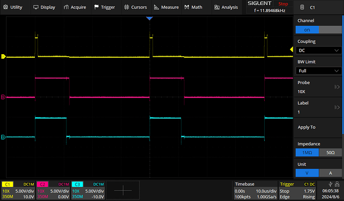
Iā€™m currently working on the Giga with SimpleFoc. At the moment, SimpleFoc will fall back to the default driver, using analogWrite() on the Giga. This causes the buzzing noise, since Arduinoā€™s Mbed-driver sets the PWM frequency to 500Hz.

I tinkered around with STM32 and Portenta code, but with both, the Giga hangs after a certain number of motors being initialized - I did not yet had time to seriously debug the issue. For the moment, Iā€™m using a hacky Mbed implementation:

#include <drivers/hardware_api.h>

/**
 3 PWM BLDC driver class

https://github.com/arduino/ArduinoCore-mbed/blob/main/cores/arduino/wiring_analog.cpp
https://github.com/arduino/mbed-os/blob/master/drivers/include/drivers/PwmOut.h
https://github.com/arduino/mbed-os/blob/master/drivers/source/PwmOut.cpp
https://github.com/arduino/mbed-os/blob/master/targets/TARGET_STM/pwmout_api.c
https://github.com/STMicroelectronics/stm32h7xx_hal_driver/blob/master/Src/stm32h7xx_hal_tim.c

*/

class MbedDriver3PWM : public BLDCDriver
{
 public:

  MbedDriver3PWM(int phA, int phB, int phC, int en1 = NOT_SET, int en2 = NOT_SET, int en3 = NOT_SET)
    : m_pwm{ 0, 0, 0 }, m_pwmPin{ phA, phB, phC }, m_pwmEnablePin{ en1, en2, en3 }, enable_active_high(true) {
    voltage_power_supply = DEF_POWER_SUPPLY;
    voltage_limit = NOT_SET;
    pwm_frequency = NOT_SET;
  }
    
  int init() override {
    for (int i = 0; i < 3; i++) {
      pinMode(m_pwmPin[i], OUTPUT);
      if (_isset(m_pwmEnablePin[i]))
        pinMode(m_pwmEnablePin[i], OUTPUT);

      m_pwm[i] = new mbed::PwmOut(digitalPinToPinName(m_pwmPin[i]));
      m_pwm[i]->period_us(40); // 25kHz
      m_pwm[i]->write(0.0f);
    }

    // sanity check for the voltage limit configuration
    if (!_isset(voltage_limit) || voltage_limit > voltage_power_supply)
      voltage_limit = voltage_power_supply;

    initialized = true;
    return 0;
  }

  void disable() override {
    setPwm(0, 0, 0);
    // disable the driver - if enable_pin pin available
    for (int i = 0; i < 3; i++)
      if (_isset(m_pwmEnablePin[i])) digitalWrite(m_pwmEnablePin[i], !enable_active_high);
  }

  void enable() override {
    for (int i = 0; i < 3; i++)
      if (_isset(m_pwmEnablePin[i])) digitalWrite(m_pwmEnablePin[i], enable_active_high);
    // set zero to PWM
    setPwm(0, 0, 0);
  }

  void setPwm(float Ua, float Ub, float Uc) override {
    Ua = _constrain(Ua, 0.0f, voltage_limit);
    Ub = _constrain(Ub, 0.0f, voltage_limit);
    Uc = _constrain(Uc, 0.0f, voltage_limit);
    dc_a = _constrain(Ua / voltage_power_supply, 0.0f , 1.0f);
    dc_b = _constrain(Ub / voltage_power_supply, 0.0f , 1.0f);
    dc_c = _constrain(Uc / voltage_power_supply, 0.0f , 1.0f);

    m_pwm[0]->write(dc_a);
    m_pwm[1]->write(dc_b);
    m_pwm[2]->write(dc_c);
  }

  virtual void setPhaseState(PhaseState sa, PhaseState sb, PhaseState sc) override {
    // disable if needed
    if (_isset(m_pwmEnablePin[0]) &&  _isset(m_pwmEnablePin[1])  && _isset(m_pwmEnablePin[2])) {
        digitalWrite(m_pwmEnablePin[0], sa == PhaseState::PHASE_ON ? enable_active_high : !enable_active_high);
        digitalWrite(m_pwmEnablePin[1], sb == PhaseState::PHASE_ON ? enable_active_high : !enable_active_high);
        digitalWrite(m_pwmEnablePin[2], sc == PhaseState::PHASE_ON ? enable_active_high : !enable_active_high);
    }
  }

  private:
    mbed::PwmOut* m_pwm[3];
    int m_pwmPin[3];
    int m_pwmEnablePin[3];
    bool enable_active_high;
};

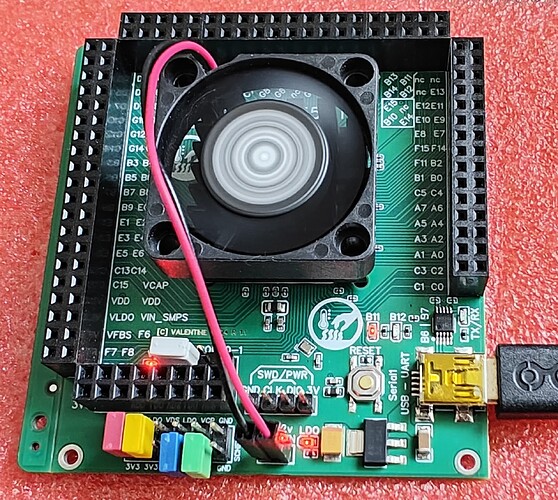
Feel free to have a look at my WIP: reufer/gigafoc (github.com)

BTW: I also have 3 pieces of P1A hardware left, if anyone is interested - however, only four motors are usable, because I used TIM2 on one instance, which is not available on the Giga. This should be fixed in P1B, which I will going to order, as soon as all components are available on JLCPCB.
1 Like

So my goal would be to support both ultimately:

The portenta, portenta lite, nicla and giga boards via arduino framework using mbed, in our portenta driver, but certainly bypassing the mbed layer for dealing with PWM and ADC configuration.
The reason being to make it easy for people to use the original Arduino boards, where the framework is based in mbed.

But actually I totally hate mbed and would not want to use it myself - hence the actual goal would be to support the dual core H7s without mbed, using just our STM32 drivers and stm32duino.
But atm stm32duino isnā€™t quite ready for this itself, so it may take a bit of time.

Regarding your code, is the PWM centered (up-down mode) in this configuration?

Thanks for the response and help. I tried changing the PWM frequency with the statements analogWriteFrequency(PWM_PIN1, 20000); // 20kHz but the mbed OS does not recognize the function. I found another mbed method as shown below to change the PWM frequency.

PinName pwmaPin = digitalPinToPinName(3);
PinName pwmbPin = digitalPinToPinName(9);
PinName pwmcPin = digitalPinToPinName(11);

void setup() {
mbed::PwmOut* pwma = new mbed::PwmOut(pwmaPin);
pwma->period_us(100);
mbed::PwmOut* pwmb = new mbed::PwmOut(pwmbPin);
pwmb->period_us(100);
mbed::PwmOut* pwmc = new mbed::PwmOut(pwmcPin);
pwmc->period_us(100);

When I first put these statements at the top of the Setup(), I found that the motor.init() function overrode whatever was set. If you put these statements after the motor.init() function, it does seem to change the PWM period/frequency. I found that if I set the period to 2000uS (i.e. 500hz) it performed and sounded exactly the same as the original issue. If I changed the period to 1000uS (i.e. 1000Hz), it was higher pitched and a little less noisy. When I changed it to 500uS (2000Hz), it was higher pitch and became erratic. I tried changing it incrementally up to 20,000Hz and it no longer functioned (or made noise).

My application is for angular positioning. I do hope you will support this for mbed as I spent far too much time trying to get my application working with an STM32F767 with a long list of problems and issues and poor tech support from STM.

I get the impression that with these very fast processors, the FOC loop is overrunning the PWM period at lower PWM frequencies. This does appear to need help at the driver level. This combination of having the FOC running on the separate M4 core and the main control system running in the M7 processor is an awesome combination that I would really like to get working as it opens up a lot of good opportunities for improvement.

Thanks again for all your help and input.

:slight_smile: we share the same dream!!!

I will try to work on this soon. I have already bought a bunch of the hardware, so really I should get going on it.

I think your mbed code is headed in the right direction, but PWM needs to be centered, and like you say the driver level code probably needs some workā€¦

Really? Why would someone choose the slower M4 core for the FOC loop?
Just because it is (currently) easier to program, I guess?

Itā€™s not:

mbed-os/targets/TARGET_STM/pwmout_api.c at master Ā· arduino/mbed-os (github.com)

And with the default PWM-Pinmap, there are not even synced at all, since different timers are used.

I do. Iā€™m working on a remote camera controller with haptic inputs (3-axis joystick, zoom rocker and focus wheel) and the M7 will run the GUI, Ethernet and controller code, while the M4 runs SimpleFOC exclusively.

2 Likes

Because this M4 will be more than fast enough to run sfoc, and the M7 can do harder jobs like motion planning, playing audio or whatever

1 Like

Anyone making any progress on this?

Iā€™m back from vacation and Iā€™ve made a start. Iā€™ll continue tonight after workā€¦

1 Like

Thank youā€¦It is very much appreciated.

Any clues yet as to what is happening?

Hi,

It turned out to be a bit more work than I anticipatedā€¦ and I have been very busy with work lately.

But recently Iā€™ve completed my code changes and have tested them on STM32F4 so far. Iā€™ll try to test on STM32H7 really soon.

I have taken a different direction - Iā€™m not a fan of mbed, and we already had a very capable driver for STM32 chips, but based on stm32duino. Hence it was not compatible with Arduino Portenta, Nicla or Giga boards, which have software stacks based on mbed rather than stm32duino.
So what Iā€™ve done is take our STM32 driver code and made it use the HAL library level only. In this way we donā€™t need a seperate mbed based driver and can just use the STM32 driver for all the STM32 based boards. Thatā€™s the theory. Iā€™ve checked that the code compiles on H7 (using the M7 core so far, but Iā€™ll check M4 as well) but still have to dig out the Portenta and Giga boards and run some tests.

In the meantime the code is here (work in progress):

1 Like

Great! Looks promisingā€¦I hope the next testing goes wellā€¦

Thanks againā€¦

I just completed my own version (much much cheaper) based on 144 pin H755Z (dual core), I will try when I get time. I want to try the multi-motor.

Cheers,
Valentine

PS The board unfortunately is not suitable for hobbyists as Arduino doesnā€™t allow for multi-core as well as certain clock / power / memory low granularity controls when you target the board directly. I had to do certain STM Cube tricks to make it work. May be if we create a variant it will work, but not sure how to program the C4 core.

PPS @runger if you are keen, I can mail you a copy of the board to test, if you want to make a variant.

Hey,

I had a brief look at this yesterday - creating new boards for the Arduino mbed core is definately possible, but looks like it will be quite some work.
Using the stm32duino looks like it currently doesnā€™t have a fully functional way to build a ā€œdual coreā€ application, although you can use either core individually, and presumably, with some messing around will be able to load code for both cores in seperate steps.

So working with new dual core boards is not that easy at the moment.

Iā€™m happy to help with creating a custom board definition, but it would probably take a few weeks due to work situation at the momentā€¦ so Iā€™d be happy to take you up on your offer, but if you need it quickly then probably Iā€™m not the best bet atm.