It seems like CB1, CB2, CB3 capacitors from EasyEDA project are rated to 16V, shouldn’t they be rated above the max allowed input voltage?
Yes absolutely!
Make sure to use all of them at above 30V which is the max for the mosfets.
Thank you Antun for developing this!
I would love to test this out for my project. Can you recommend a hardware configuration (motor + encoder + MCU) that is known to work at high power and high RPM with this driver? Which motor and encoder did you do your testing on?
TIA ![]()
I’d definitely go for an STM chip a G4 or an F4 at least, this way you can use the low-side current sensing class (even though it has the inline hardware) and get a very high frequency current loop.
The motor and the sensor will depend on your application. I’ve got very good results with encoders, but spi sensors are also fast and very popular. ![]()
If you want to do only the velocity control, you might also try sensorless from our drivers library. It’s still a bit under tester but at quite a few people had some good results with it already ![]()
I develop a custom tadpole trike and I am looking for a suitable board.
I read on the oshwlab page that you linked, that the project is only meant for internal resistance of 10 ohms and above.
You didnt meantion anything about the in the initial post itself, so I just want to be sure?
You are aboslutely right. It’s a typo, a copy+paste error ![]()
The baord is designed for high-power motors, no 10 Ohm resistance limit.
I’ve removed the line from the readme. ![]()
That is wonderful news
So I am capable to use it with brushless motors, who then power electric vehicles.
Is there something, that prevents the availability of the board in the shop?
And which motors would you recommend to use with it?
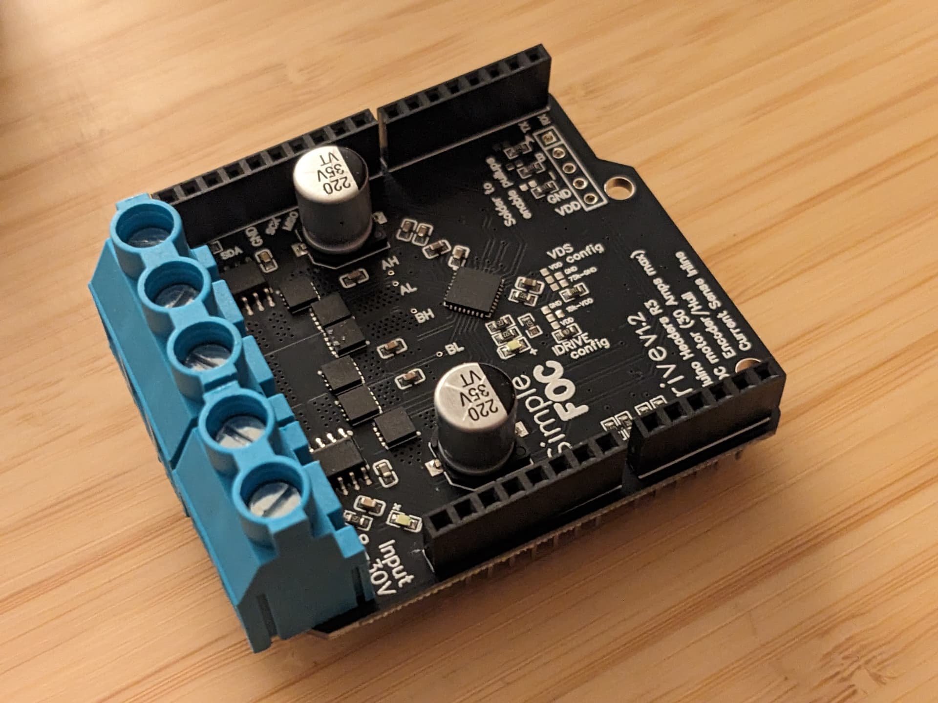
Thank you for the SimpleFOC DriveShield! ![]()
![]()
![]()
Is it possible to replace MOSFETs
BSZ0904NSI
with
ISZ0703NLS
ISZ0702NLS
ISZ034N06LM5
in order to increase max ratings for voltage and current of the SimpleFOC DriveShield?
Hi @SierraBravo,
Your mesfets look fine and the should be able to fit the 3mm x 3mm footprint.
So they should be able to increase the voltage range of the board.
BUT, if you wanna have more than 35V make sure to use the capacitors that can handle them. The electrolytic capacitors on the board are rated for max of 35V at the moment.
Also, increasing the voltage rating does not really mean increasing yhe current rating.ifyoure increasing the voltage to be able to run more current through the board, that will not be do simple. ![]()
In order to increase the current carrying capacity you’d need to increase the copper thickness and add some cooling. ![]()
Hi @Antun_Skuric ,
Thank you very much for your answer with additional explanations!
I’m considering driving e-scooter BLDC motor (42V 30A max).
What are the plans for SimpleFOC StepMini availability in SimpleFOC Shop?
Wishing you all the best!
Are there still plans, to ship this from the shop?
Hey @ShalokShalom.
I am planning to do it as some point, but not as soon as I hoped. ![]()
I’ll surely not be able to ship it before april.
Hi @Antun_Skuric, thanks so much for designing this board for us. I tried testing it but unfortunately I could not successfully solder the Arduino headers. Despite incrementally increasing the temperature and a liberal amount of flux, the solder just wouldn’t stick to the pads on some of the pins. It would just creep up the header pin instead. Perhaps we need to increase the size of the pads to make the board easier to hand solder? Or ship them pre-assembled?

Hey @Jeremiah_Rose,
Yeah, I’m aware of this issue. Those are the ground pins that are connected to the big ground plane so they are a bit problematic to solder. You just have to give it a bit of time, stay 30-40 seconds on each of those pins with your soldering iron and it should work. The same issue exists for the SimpleFOCShields as well. But it’s true that they have smaller and thinner ground plane.
I’ll add a thermal relief on the next version to make it easier to solder. ![]()
Thanks, I’ll have another go with some pre-heating from the heat gun and see if that works. And agree, thermal pads would make a great difference!
Question (maybe we should add a Q&A to the Github?) - do the jumper configurations have defaults, or do they all have to be soldered before the shield will work?
For example, is it necessary to solder all of the pin configurations on the underside of the board, or is there a default pinout?
UPDATE: looking at the schematic, it looks like the pin config does need to be soldered, there’s no default.
Hi sir @Antun_Skuric, I have successfully tested your design, thanks so much for it. Now my project needs like 10 boards like that (each will operate at 10A), will I have to adjust anything? Do I need a larger bulk caps? My plan is to stack all boards up
Hey @Jeremiah_Rose,
Nice!
Yep you’re right, I didn’t get to the docs part yet ![]()
The configuration pins are more or less the same as for the SimpleFOCShields. So the you can use the guide