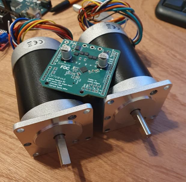
Okay this week I’ll find some time to test these ![]()
Okay so I have beene trying to test this board with the motors. One of the middle mosfets has been giving off a lot of smoke but the board still manages to drive the motor during startup. I have not managed to get it working though, it keeps on giving off a “failed to notice movement” error but I read and display the angle of the motor. ( it seems to output 3.14 when rotated a full revolution so I’m assuming its radians)
Am I doing anything wrong here:
#include <SimpleFOC.h>

BLDCMotor motor = BLDCMotor(2);

//MagneticSensorSPI sensor = MagneticSensorSPI( AS5147_SPI,53);

// BLDCDriver3PWM(pwmA, pwmB, pwmC, (en optional))
BLDCDriver3PWM driver = BLDCDriver3PWM(6, 10, 5, 8);
//BLDCDriver3PWM driver = BLDCDriver3PWM(7, 9, 6, 8);
HallSensor sensor = HallSensor(18, 19, 20, 2);

float target_angle = 0;
// instantiate the commander

void doA(){sensor.handleA();}
void doB(){sensor.handleB();}
void doC(){sensor.handleC();}


Commander command = Commander(Serial);
//void onTarget(char* cmd){ command.scalar(&target_angle, cmd); }
void onMotor(char* cmd){ command.motor(&motor, cmd); }

void setup() {

  // use monitoring with serial
  Serial.begin(115200);
  SimpleFOCDebug::enable(&Serial);

  driver.voltage_power_supply = 20;
  driver.init();
  motor.linkDriver(&driver);

  sensor.init();
  sensor.enableInterrupts(doA, doB, doC);

  motor.linkSensor(&sensor);

  //motor.controller = MotionControlType::velocity;
  motor.controller = MotionControlType::torque;

  motor.PID_velocity.P = 0.2;
  motor.PID_velocity.I = 20;
  motor.PID_velocity.D = 0;
  // default voltage_power_supply
  motor.voltage_limit = 6;

  // velocity low pass filtering time constant
  motor.LPF_velocity.Tf = 0.01;

  // angle loop controller
  motor.P_angle.P = 20;
  // angle loop velocity limit
  motor.velocity_limit = 50;


  motor.init();

  motor.initFOC();

  motor.target = 2;

  //Serial.begin(115200);
  Serial.println("Motor ready.");
  //Serial.println("Set the target angle using serial terminal:");
  _delay(1000);
}

void loop() {
  // main FOC algorithm function
  motor.loopFOC();

  // Motion control function
  motor.move();
  //sensor.update();
  // display the angle and the angular velocity to the terminal
  //Serial.print(sensor.getAngle());
  //Serial.print("\t");
  //Serial.println(sensor.getVelocity());
  // user communication
  command.run();
}
Oh wow! That is definitely not a good thing. Make sure that the init current is not too high!
motor.voltage_sensor_align = 0.5; //Volts
You motor has 0.1 Ohms phase resistance so with 0.5V alignment voltage you should have around 5A current.
This seems to be a sensor issue. You should have exactly 2pi radians for one rotation (2pi is around 6.28 radians).
But “failed to notice movement” arrives if the sensor reads almost zero movement during the initFOC. So if your motor moves, this probably means that the sensor does not read its position properly (or is not read properly).
Okay I wired up a new board, added in the statement and checked the number of poles to get 6.28 radians per revolution.
I put the statement before the motor.init function.
void setup() {

  // use monitoring with serial
  Serial.begin(115200);
  SimpleFOCDebug::enable(&Serial);

  driver.voltage_power_supply = 20;
  driver.init();
  motor.linkDriver(&driver);

  sensor.init();
  sensor.enableInterrupts(doA, doB, doC);

  motor.linkSensor(&sensor);

  //motor.controller = MotionControlType::velocity;
  motor.controller = MotionControlType::torque;

  motor.PID_velocity.P = 0.2;
  motor.PID_velocity.I = 20;
  motor.PID_velocity.D = 0;
  // default voltage_power_supply
  motor.voltage_limit = 6;

  // velocity low pass filtering time constant
  motor.LPF_velocity.Tf = 0.01;

  // angle loop controller
  motor.P_angle.P = 20;
  // angle loop velocity limit
  motor.velocity_limit = 50;
  motor.voltage_sensor_align = 0.5;

  motor.init();

  motor.initFOC();

  motor.target = 2;

  //Serial.begin(115200);
  Serial.println("Motor ready.");
  //Serial.println("Set the target angle using serial terminal:");
  _delay(1000);
}
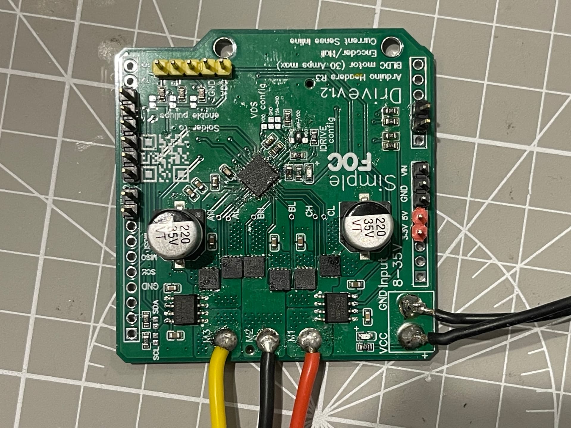
And it still gave off smoke and couldn’t see the sensor. I can get the sensors to display the position on the serial terminal no problem so they are definitely working. On one revolution the serial output goes from 0 to 6.28.
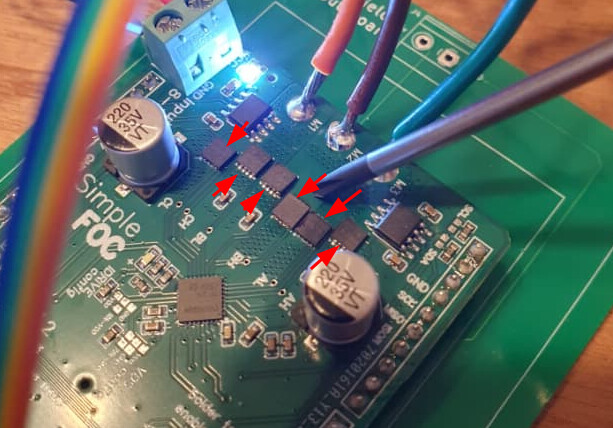
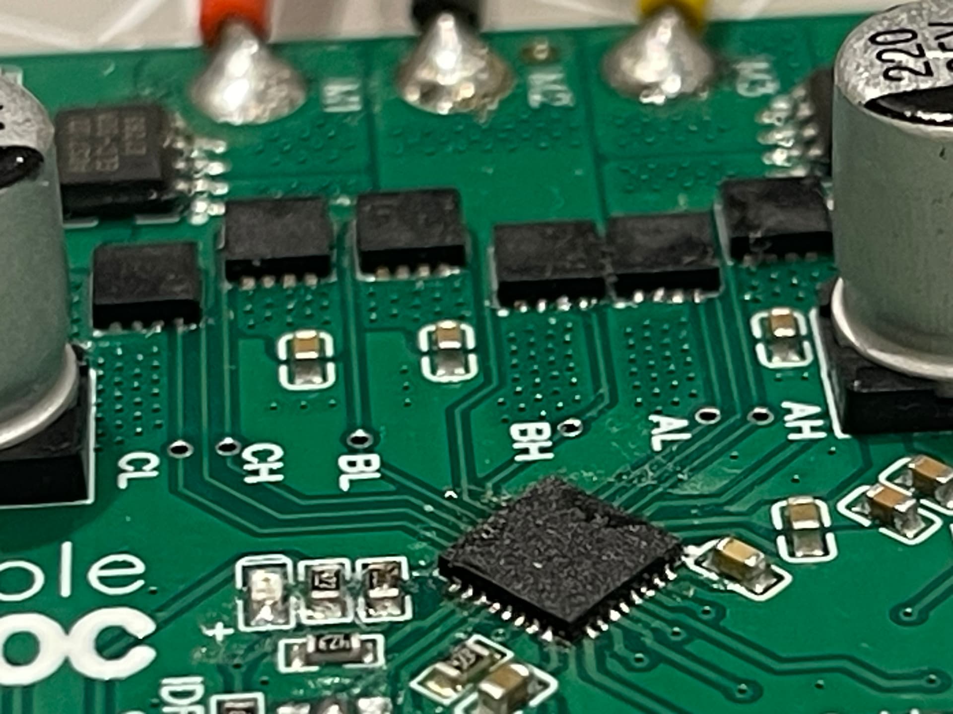
The smoke came from this mosfet on both boards,

As you can see it doesn’t looked burnt out. I’m sure it’s not doing so well though.
huh, this is strange ![]()
Just to confirm, you have already used these boards to run other motors with lower phase resistance right? Like gimbal motors?
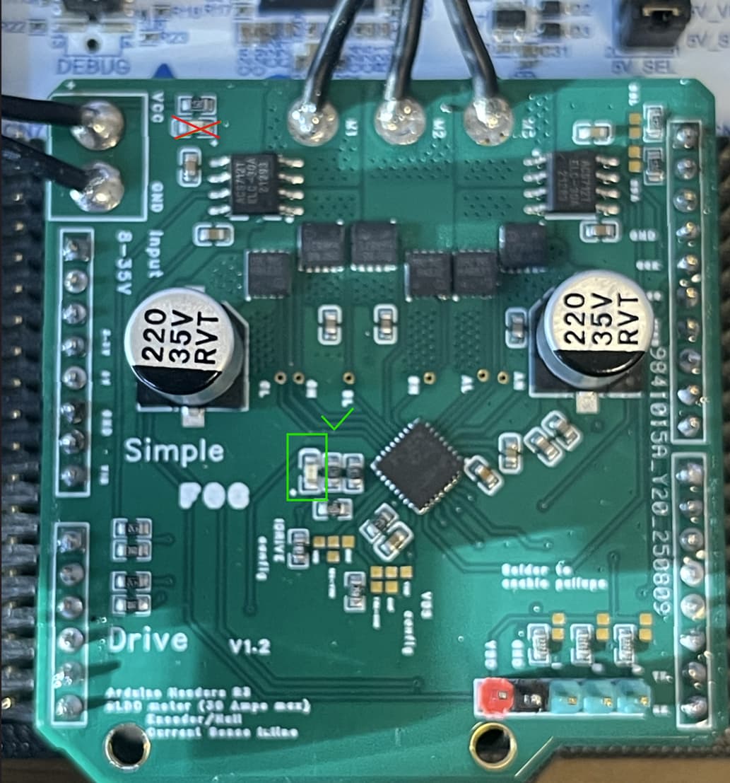
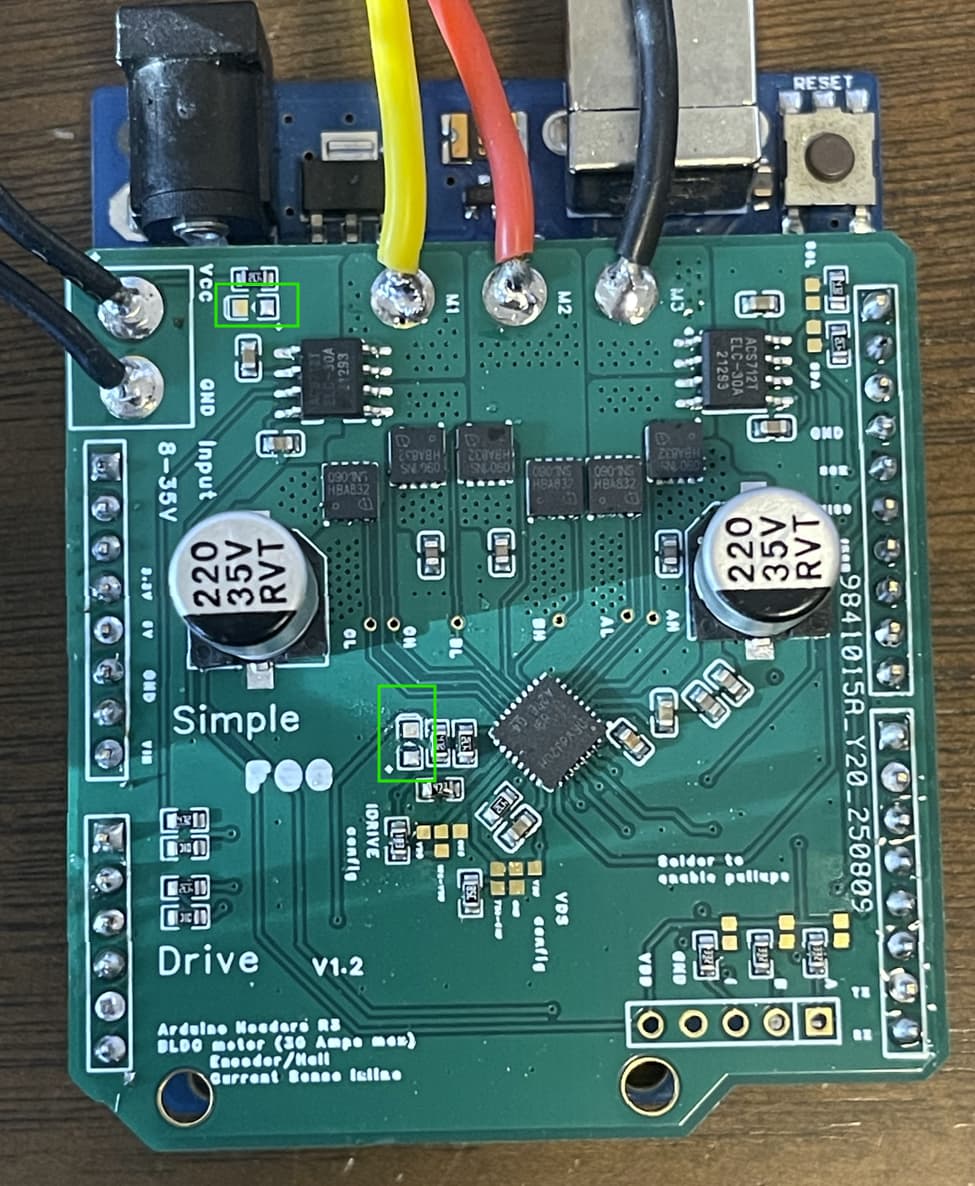
What you could try is to limit the IDRIVE current to 30mA. The defualt value is 120mA and that might be to much. You can set this value using this soldering pad:

Could you also show a picture of your board from above?
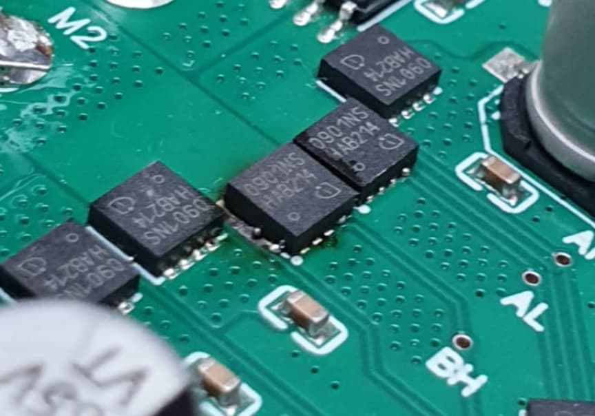
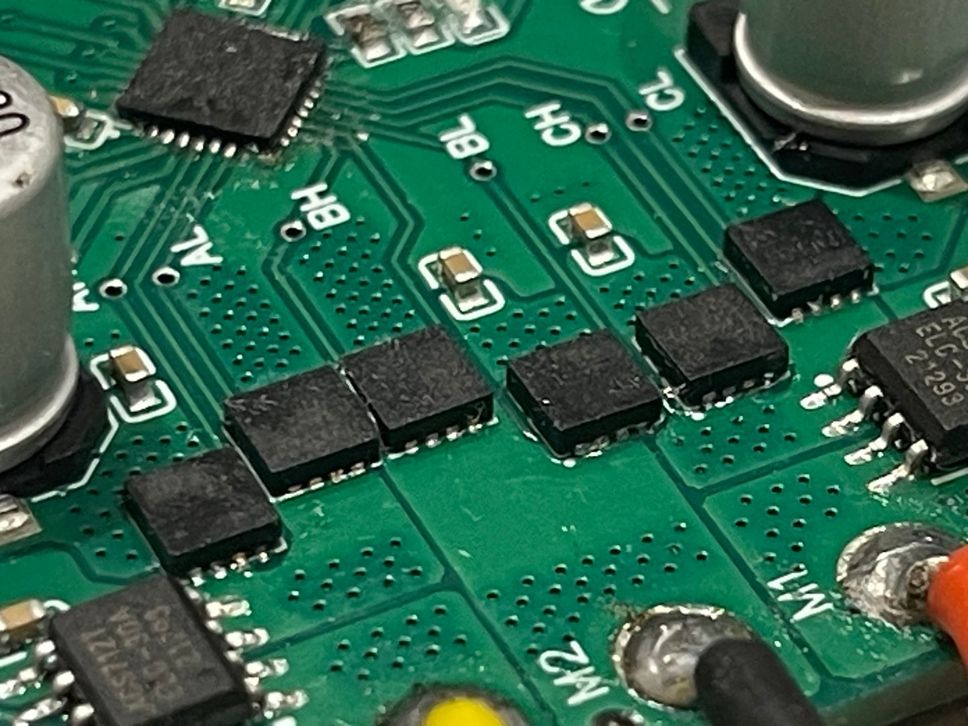
In the images it seems like the mosfets are a bit shifted ![]()
Is this just an illusion due to the camera angle?
The smoking mosfet is different dimension. Compared to the one at the right the bottom edges are aligned and the upper aren’t… it seems like the size is different. Are they different version? Is there a problem in the soldering?
Is it maybe rotated? The picture provided isn’t very clear, and I can’t see the markings…
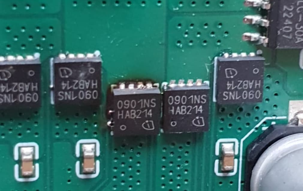
If you can take a high res picture from above where we can see the markings on the chips then we can compare and check for correct orientation…
Hey guys, sorry I’ve been away a while. I just started a new job. I am now an electronics engineer, moved on from mostly working mechanical stuff ![]()
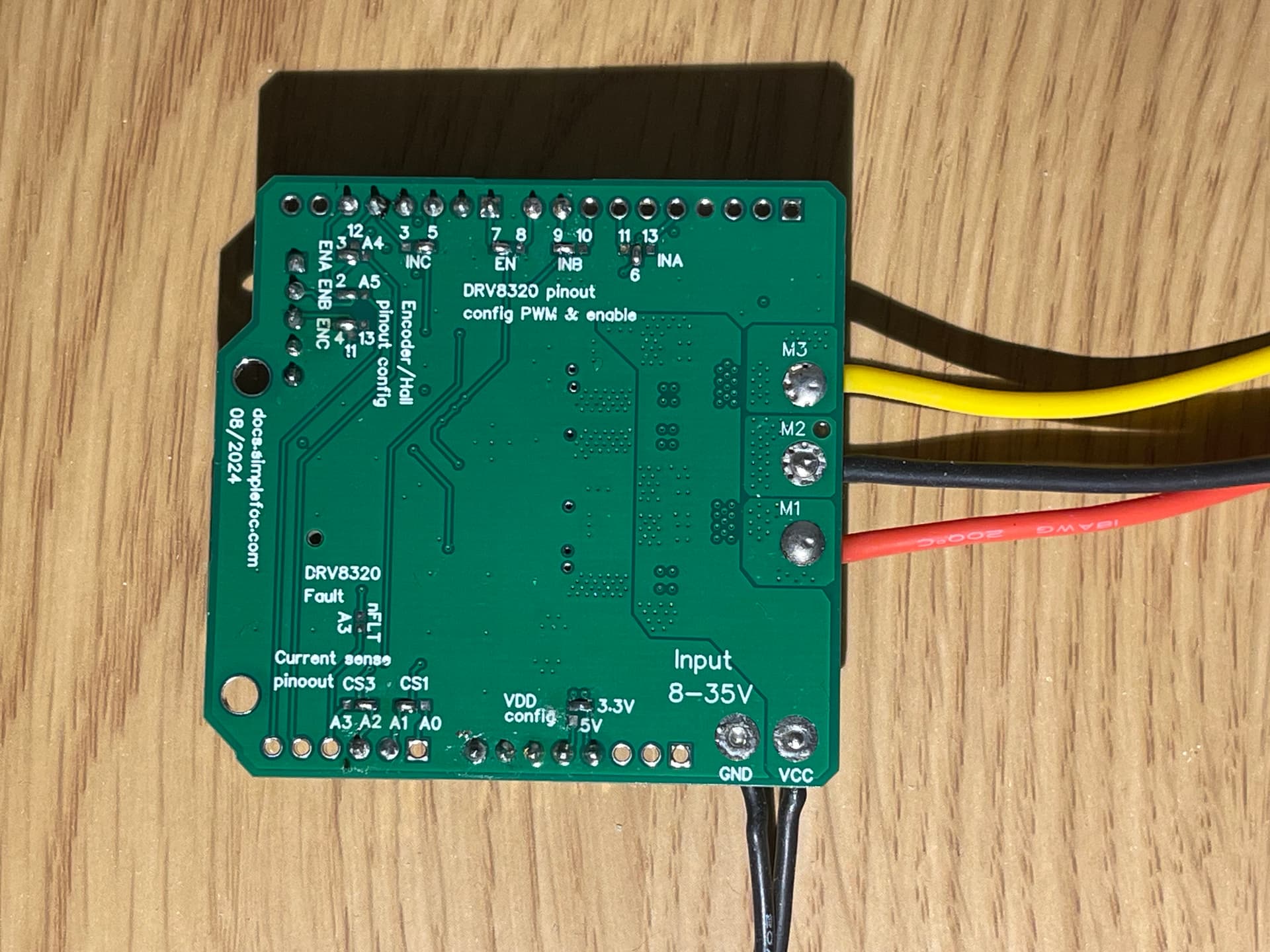
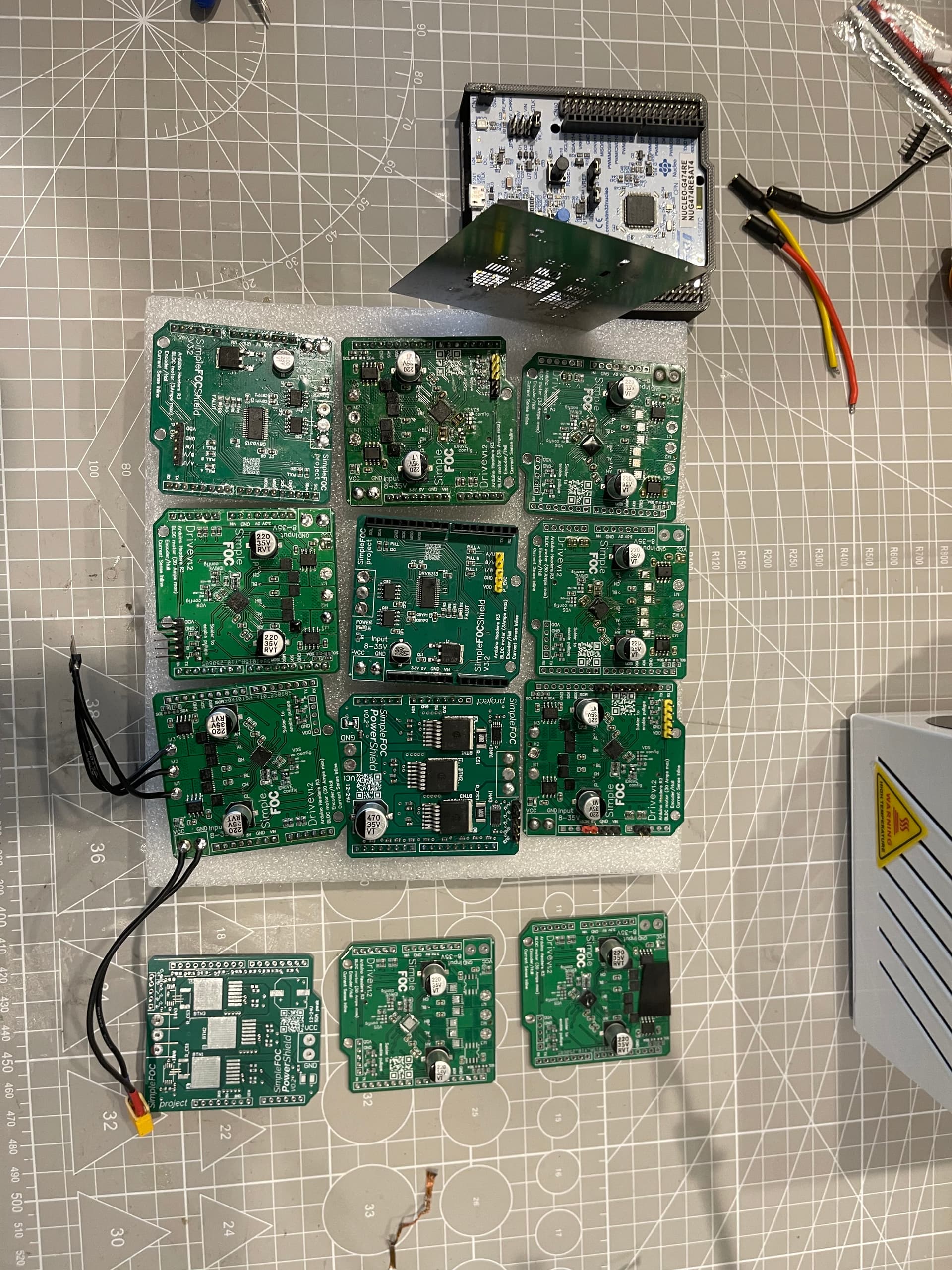
Here’s more pics of the boards.

Here’s what the untested boards look like
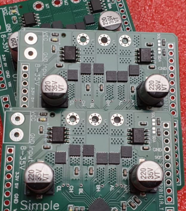
I’m not sure how I feel about the tiny form factor topologies. Sure they are necessary for mobile devices but they are not exactly easy to work on if something goes wrong.
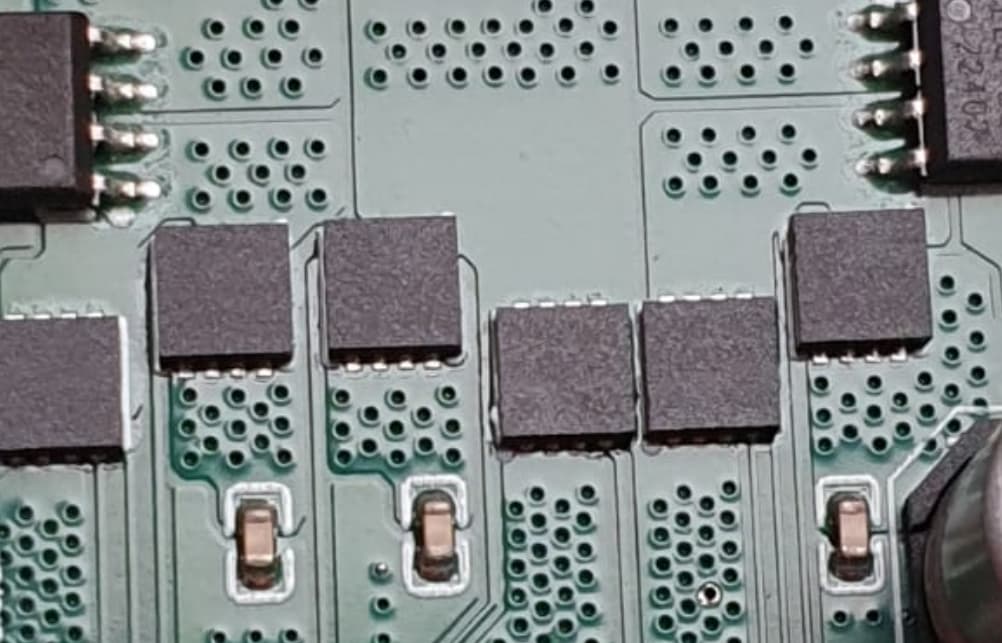
It seems to me, there’s was too much solder paste under the chip, which had caused shorts.
The burnt one clearly shows beads of solder squeezing out from under the chip.
Even the unused PCB shows a hint of abundant solder.
Better check all pins for continuity against GND with a multimeter.
I agree with @o_lampe , the FETs look badly soldered. Two of the FETs look damaged by heat, and there is solder coming out of them from underneath.
Even some of the FETs without visible heat damage have solder beads coming out of them…
Maybe it’s caused by a too big GND-cooling pad definition in the parts footprint?
It might be an issue @Antun_Skuric could check. The FETs datasheet will surely mention something about the best size and not all generic footprints can be used.
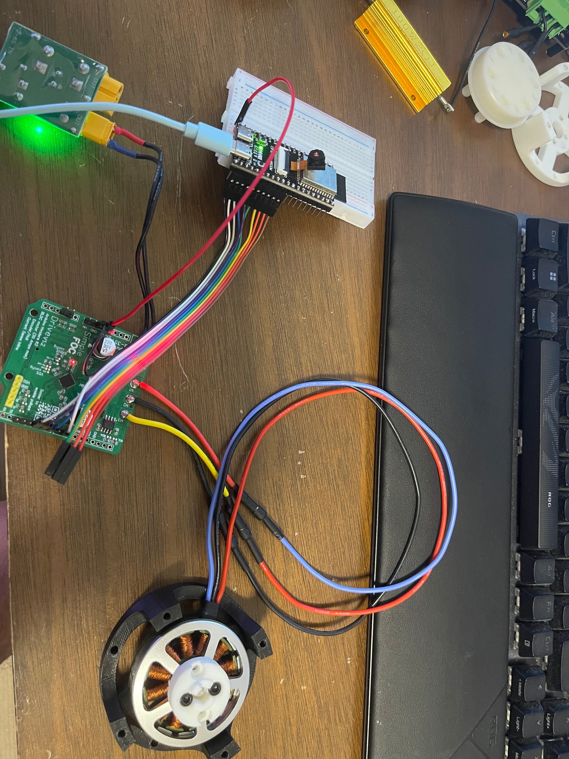
Hi guys,
Can I get some help for setting up drive shield.
I can not get open-loop work with SimpleFOC open loop velocity example.
My observation:
- on board encoder pins works.
- three motor phase voltage float between 2.9V to 3.6V, when code set motor target as “2”.
- LED 1 full on, LED 2 on but is like 30% brightness only.
- Resistance between VCC and Ground: 5.78MΩ
- Resistance between motor out put ABC are: 1.5to 2.5 MΩ or 5 MΩ .
- I made few boards, and I am 90% confident there should be no soldering issue, I am suspected this is either bad component or my hardware config issue.
- I also add IDrive config as suggested above, still same result.
- Looks like PIN_FAULT read LOW.
- Also VIN read 0 voltage, I need power MCU and driver separately ( same method works for power shield, as long as they are share ground.)
Any though would be helpful.
Thanks.
After more testing, although still I am not able to get Drive shield work, with same issue, Fault indicator is on, I would still like to share what I found and learn ![]()
overview :
- Shield V3.2 is really good starting point, I am able to get full current close-loop working with just follow the documents.
- Power shieldV0.2 is also easy to build. It is simple and worked as dream.
- Drive Shield require experience and debug knowledge to build. I haven’t try JLC-STM yet, maybe this is my next step.
Learned:
- Hardware config is important and can NOT get it wrong, unless use ESP32, UNO and Nucleo board are imitated option for the config, must follow documents.
- LED direction is reverted on
Pick Placefolder, please be careful, green mark is negative, follow theSimpleFOC-DriveShield/image/top.jpgimage and+mark on PCB board make sure. (Not install fault LED somehow give me higher success rate when building them) - Power shield V0.2 board need include current setting in code to make full board working, no need to test open loop, current setting are must.
ACS712ELCTR-05B-Tand orACS712ELCTR-30A-Tare cheap, but easy to buy used or faulty one unintentionally, always test if part is working before solider them on board.- All code from
examplewill work as expected, no need to modify for POC work. - UNO ram size (32kb) is too small for latest SimpleFOC code with current code, use UNO R4 or Nucleo G4 Board instead.
Next:
I will order STM for this driveshed from JLCPCB and verify POC work, I will update my testing result if working.
Thank you
A quick replay, I finally got everything working now!
Things I did differently:
- Used 4 layer gold PCB board (
ENIG surface finish). - Skip LED1 ( power LED), this is key reason I got it working.
- LED1 burned right after power on, but bord works, so I test second board without any led, still working.
- To be honest, I tried both direction for LED, only bad LED works… LOL
Some pictures:
- LED power is burned, fault LED works, but stay off.
- Second board, I skipped both LED, and board works.
This all goes to show how much work it is to get even apparently a straightforward board working. This is exactly why we should pick/concoct one board and get it working thoroughly, not leave everyone to do this kind of thing yet again with another board. I mean, the power led?
I do agree that these efforts would make much more sense if joined, so that’s kind of the point with SimpleFOC. Its open source and community driven. The board is on github and easy-eda and you can easily contribute to it if you want/have time.
In @pleycothh case, I would expect that most of the issues @pleycothh probbaly had are related to the manual fabrication of the board. As opposed to SimpeFOCShield v1/2 the Driver shield is not designed to be done in such a way and I would not really suggest doing so. ![]()
I admire your effort @pleycothh, I’d not be as patient or competent ![]()
But yeah, I’m not sure about the LED. It seems like a such a random problem that is true.
Hi Antun, thanks for your reply, and thanks for sharing this project.
I agree, and I can confirm this is true — build quality was the only real issue I faced. After a few months of learning and testing, I found that soldering quality is the main challenge when building an FOC board. Even when the board looks fine to the naked eye, under a microscope the solder joints can be poor. I also short multiple resistors per board easily.
In conclusion, for beginners I would highly recommend either using an STM service as reference design or buying a ready-made board as a reference. Then you can compare resistance and voltage measurements against your own hand-soldered board. This makes debugging much easier.