SimpleFOC DriveShield - A big (more powerful) brother of the SimpleFOCSheild

Hi guys,

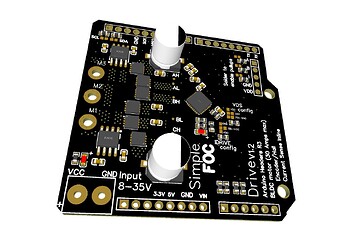
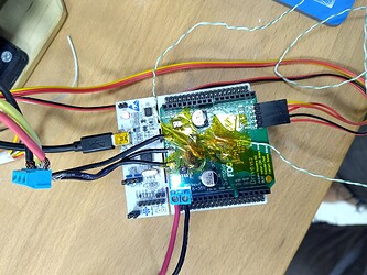
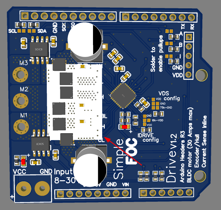
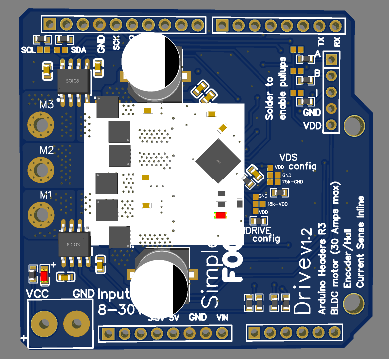
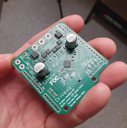
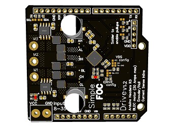
I’ve been following the footsteps of many of the community members especially Valentine and created my take on the more powerful SimpleFOCShield. I’m calling it SimpleFOC DriveShield. :smiley:

The board is the big brother of the SimpleFOCShield and is designed to drive motors with higher current requirements, up to 30Amps. The board is created with the same philosophy as the SimpleFOCShield - to be simple to use, low-cost, and completely open-source.

Additionally the aim of the board is to serve as a template project for the community to build their own motor drivers.

  • The board is relatively simple and can be easily modified to fit different requirements
    • change the mosfets
    • change the gate driver
  • The board is designed in EasyEDA and it’s easy to manufacture with JLCPCB

Components

  • DRV8320H gate driver
    • Hardware configuation
    • 3PWM
    • Protections: undervoltage lockout, charge pump fault, MOSFET overcurrent, MOSFET short circuit, gate driver fault and overtemperature
  • BSZ0904NSI mosfets
    • Standard 3mm x 3mm footprint (can be easily exchanged)
    • Max current: 75A
    • Max voltage: 30V
    • Max temp: 150C
  • ACS712:
    • 30Amps bidirectional
    • In-line current sensing

Features

  • Boards absolute max ratings
    • Max current: 20A continuous (peak 30A - measured),
    • Max input voltage: 30V
  • Stackable: running 2 motors in the same time
  • Encoder/Hall sensors interface: Integrated 3.3kΩ pullups (configurable)
  • I2C interface: Integrated 4.7kΩ pullups (configurable)
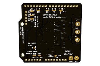
  • Configurable pinout: Hardware configuration - soldering connections
  • Arduino headers: Arduino UNO, Arduino MEGA, STM32 Nucleo boards…
  • Open Source:
  • Low-cost (relatively): Estimated price of 25-40€ - Will be available in the SimpleFOC shop

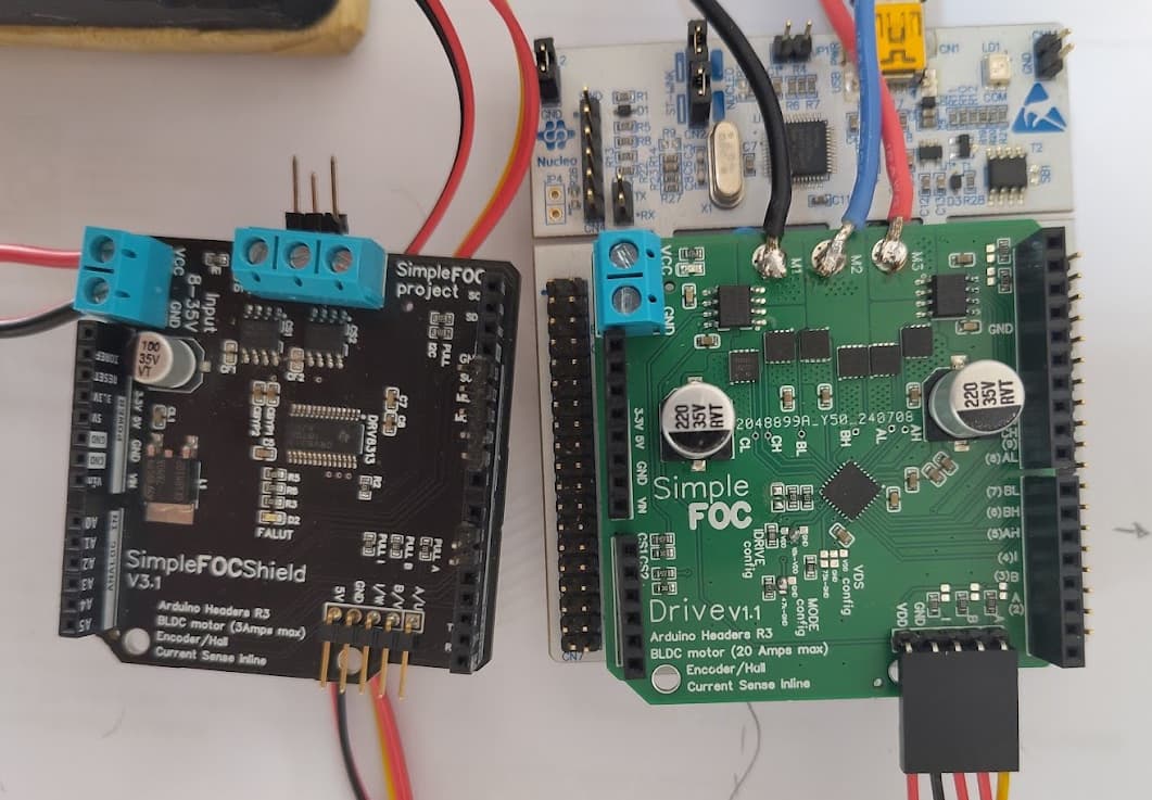
Size comparison with SimpleFOCShield v3

Temperature characteristics

This board can measure the phase currents up to 30Amps, so it is intended to be used in applications that require current draw up to around 20Amps continuous. For higher currents especially in the range of 15-30Amps the board can get quite hot. Depending on the copper thickness of the PCB chosen when ordering the board the temperature can vary. Also, the board could be fitted with a heatsink to improve the thermal discipation.

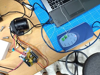
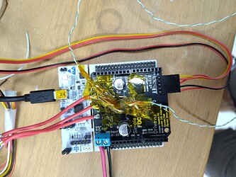
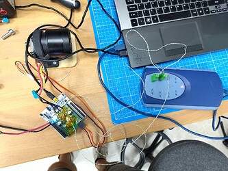
So I’ve wanted to quantify the temperature characteristics of the board when a continuous current is applied to the motor. The measurements were done with a relatively constant ambient temperature of around 25°C. The board was powered with 24V. The motor was run at very low speed (0.1rad/s) in the open loop and the current (q component) was set to 10, 15 and 20 amps for prolonged periods of time. I’ve measured the temperature on the top of the board on the DRV8320H gate driver and the BSZ0904NSI mosfets. I’ve used the PICOLOG TC-08 thermocouple data logger to do the measuring.

I’ve tested the same board with two different copper layer thicknesses

  1. Standard 4-layer:
    • 1oz (35um) copper thickness on top and bottom layers,
    • 0.5oz (17.5um) copper thickness on inner layers
  2. Thick 4-layer:
    • 2oz (70um) copper thickness on top and bottom layers,
    • 0.5oz (35um) copper thickness on inner layers

Standard 4-layer PCB (1oz top and bottom, 0.5oz inner layers)

Thick 4-layer PCB (2oz top and bottom, 0.5oz inner layers)

Experiment results

Here is the table of the results

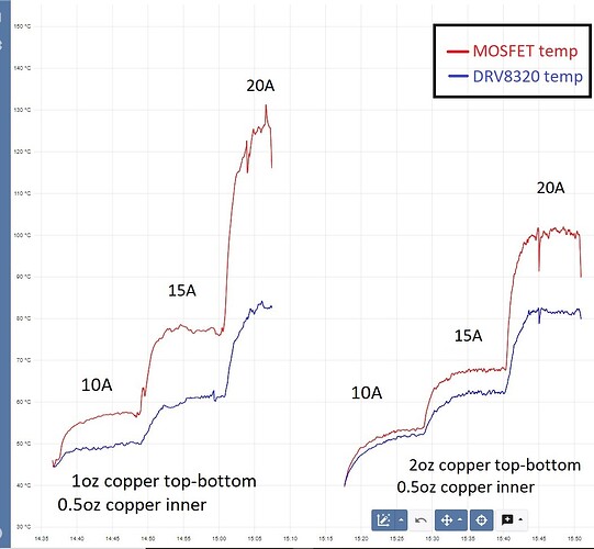
Current [A] Standard 4-layer MOSFETS Thick 4-layer MOSFETS Standard 4-layer DRV8320 Thick 4-layer DRV8320
10 57°C 53°C 50°C 52°C
15 78°C 68°C 62°C 62°C
20 125°C 100°C 82°C 82°C

And here is the curve from the experiment:

So the results seem to suggest that, as the BSZ0904NSI mosfets are rated for temperatures up to 150°C and the DRV8320H gate driver up to 125°C, the board can be used up to 20Amps without additional cooling.

However, I would definitely recommend using a heatsink or a thicker copper PCB (2oz top and bottom layers) for currents above 15Amps continuous.

So there it is guys. Even though this is the first real iteration of this board and I’m sure there will be many more in the future, I am pretty happy with this board for now :smiley:
The board will be available in the shop at some point in the future, I am not really sure when though, not before November.

I’d be very happy to hear your comments about it!
Cheers,
Antun

EDITED: I’ve forgotten that I’ve tested up to 20Amps not to 30Amps continuous as in my original post!
12 Likes

@Antun_Skuric

This is awesome! Thank you.

Cheers,
Valentine

1 Like

Hello

This looks very nice and promising, looking forward to trying it out.

I already love it just because of this:

Stijn

This is awesome, I would like to try out some higher power drivers so I’d be keen to get some of these fabricated.

Can I place a heatsink on it and still stack it for two motors?
What would the heatsink look like? One strip above all six FETs?
Are the FETs and current sensors same height? Looks like it would make it difficult to fit a sink, if they’re not.

Is cooling the bottom side an option?

THX
Olaf

Hey @o_lampe,

Yeah, its a bit crammed. The FETs and the as712s are the same height, so you could potentially put a heatsink on all of them.
But the better option would be to put a heatsink on the FETs and on the DRV8320.

I’ll try to make it a bit easier to put a heat sink in the next versions. The main limitation is the disctance between the caps, it should be a bit larger, for now its 22-23mm.

I’ve tried with a simple 19x14cm heatisink (I’ve had it on hand - aliexpress link) that was placed almost exclusively on the FETs

Here is how I’ve placed it more or less.

A better option would be something like a bit wider up to 23mm. It could also go up to 25mm at lenght and cover the drv8320 as well. Something like this:

The heatsinks that I’ve had are 7mm high so you could use them and still stack two shields.

But yeah, the larger+higher they are the better their temperature discipation so it’s a trade-off.

So yeah, I’ve not done any real study on the heatsinks yet. I’ve just tried with some that I’ve had from earlier projects and seen a clear positive impact right away. But no quantitative data to support it. :smiley:

What are the currents that you’re aiming for?

2 Likes

I still have some smaller 6.5" hoverboard motors where I grilled their original controller while hacking them for simpleFOC.
They are rated 300W@36V, but I intend to use them with 24V.

I got your board made :slight_smile:

Hopefully I’ll have time to test it this week.

3 Likes

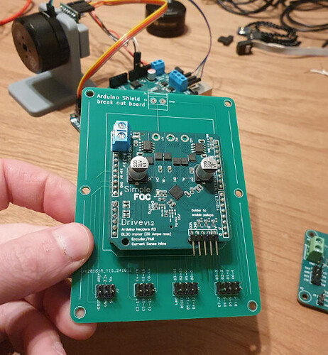
Seems I can’t embed more than one image as a new member.

I also made up this breakout board for Arduino shields. I’d like to try get SimpleFOC working off a pi pico and this seemed like a handy way to test the shields with other hardware.

4 Likes

@Antun_Skuric For starters I’ll use my old Arduino Due boards, but if I’d look for a Nucleo, which MCU would suit best?
I guess the DriveShield is 5v and 3.3V compatible?

Awesome, :smiley:
I’m looking forward to hearing your thoughts!

I would not suggest using DUE. I mean, it will work, but the support for DUE is the worst one with respect to all the other Arduino boards. I think that the PWM timers are not aligned on DUE. For gimbal motors, this is not a big deal, as the peak currents produced by a potential misalignment are not too bad, but on higher power motors, this will be an issue.
I honestly do not remember any more if we synched the timers on Due or not, but what I am sure is that the drivers for Due were not updated for a few years now. So I’d argue to try to avoid it :smiley:

I’d suggest a nucleo board, either a f4 or g4 nucleos (mabe the g4 would be my preference).

Yeah, DriveShield is intended to be run at 3.3V. It will support 5V as well, no problem.
But the current sense analog output is in the 3.3V.

1 Like

So far the little solder jumpers on the back have been very fiddly to solder. I suggest making them bigger on the next version of the board.

Haven’t got to power up yet.

Very interesting… this can make competition with Odrive and other high power driver. But as I see from the feature list there is no SPI protocol. Isnt’it? That could be very useful for magnetic encoder (AS5048A) which are very thin and don’t need the shaft for mechanical connections… there are some very interesting motors that have a groove for that encoder, GIM motors.

I do agree, I’ve reduced their size signficantly from the simplefocshield size, but it’s a bit too small now. I mean, it is ok for 2 or 3 pin solder connections, but when there are four pins it’s hard to be precise. :smiley:
I’ll make sure to make them bigger for the next release.

This board is just the driver (no sensor integrated), it’s intended to be used with a board that has UNO R3 headers, like stm32 nucleos for example.
So you are free to use any sensor/protocol that is supported by the SimpleFOC library. :smiley:

1 Like

Oh, sure! wrong comment mine… So let drop a line when the board is in the shop!!!

@Antun_Skuric I just read in another thread, that simpleFOC doesn’t support current sensing for more than one motor at the moment.
I guess that also applies for stacking the DriveShields?
I’ve had good results with the voltage based current estimator, but would like to implement some overcurrent protection independent from the motor control loop. ( eg. ACS71 raises a flag, which the main loop checks next iteration)

Hey @o_lampe,
We do support more than one motors with inline current sensing, but not with low-side. All our boards use inline current sensing, so you should be fine.

1 Like

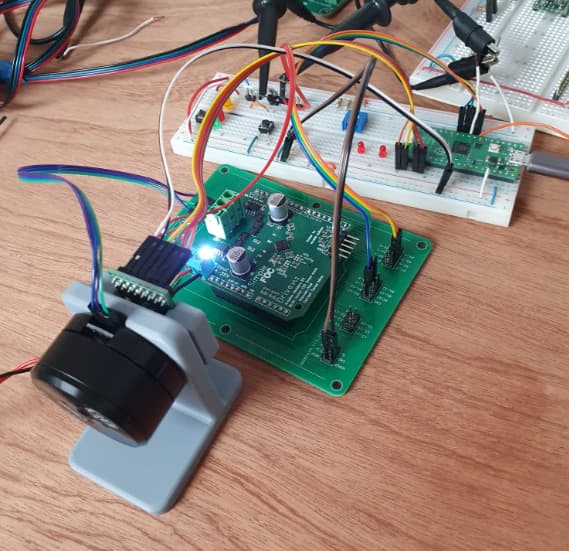
Powered up and working! The only problem is I’m going to need a bigger motor to test it properly haha

1 Like

You could try multicopter motors. They are a big step hotter than the gimbal motors. Unfortunately there is a big power-gap between gimbal and drone motors.
I’ll try mine with 6.5" hoverboard wheels soon.

I received my samples yesterday (THX Antun :+1: )
At first glimps I’m concerned about the caps: they are higher than the headers.
Not sure if that’ll be a problem for stacking the boards?