Hello! I’ve been working on getting CAN bus working on @Valentine’s QVADRANS board using a hat with a CAN transceiver with @Grizzly’s SimpleCanLib (forked to add support for pi picos using the CAN2040 library).
I’m able to send & receive CAN messages between picos and a B-G431B-ESC1 board and they all look as expected on my logic analyzer, but once I get code uploaded and booted on the QVADRANS I don’t see any attempts on the bus to send messages, just silence. It’s not hanging since I can still debug it and talk over UART, though. It also doesn’t ack messages sent by another device on the bus.
At one point a few months ago I was able to receive messages on the QVADRANS, but I can’t seem to replicate that since I was in the middle of moving and poorly documented it.
Do you all have any advice for debugging this? I get the feeling that something in my CAN configuration is off, but I haven’t made any headway on where to dig into that yet.
Below is my platformio.ini for the QVADRANS/generic board as well as the (working) ESC1 board, and I’m using CAN Rx/Tx as PA11 & PA12.
[env:generic_g431b]
platform = ststm32
board = genericSTM32G431CB
framework = arduino
upload_protocol = stlink
debug_tool = stlink
lib_archive = false
build_flags =
	-D ARDUINO_GENERIC_G431CBUX
	-D STM32G4xx
	-D HAL_FDCAN_MODULE_ENABLED
	-D PIO_FRAMEWORK_ARDUINO_NANOLIB_FLOAT_PRINTF
	-D BAUDRATE=115200
	-D SERIAL_UART_INSTANCE=3  # configure default serial object
	-D PIN_SERIAL_RX=PB11 # configure default serial rx/tx
	-D PIN_SERIAL_TX=PB10
lib_extra_dirs =
	../lib


[env:disco_b_g431b_esc1]
platform = ststm32
board = disco_b_g431b_esc1
framework = arduino
upload_protocol = stlink
debug_tool = stlink
lib_archive = false
build_flags =
	-D HAL_FDCAN_MODULE_ENABLED
	-D PIO_FRAMEWORK_ARDUINO_NANOLIB_FLOAT_PRINTF
	-D BAUDRATE=115200
lib_extra_dirs =
	../lib
Can you measure anything between transceiver and MCU?
1 Like
Hi Pete,
Make absolutely sure that your timing parameters for CAN are correct, maybe try a few different calculators. If the timing is out of spec, I have seen that just no messages are emitted at all from the xcvr. (this depends on your system clock, peripheral clock, and specific choice of xvcr chip so is different for pretty much every setup)
1 Like
@Grizzly Yeah, everything looks good there too.
@VIPQualityPost Thanks, I’ll take a look at them. I’ve been using the same settings that were used for the ESC1 board since the QVADRANS also uses the G431CB(U6?), so I figured that’d likely work as-is. That being said I never really got to taking a good look at them to make sure, so now’s as good a time as any!
This is true, they are the same chip, but I do recall that ST likes to use 16MHz crystal oscillator, but that is more uncommon for other designs, I think 12MHz is more typical (what I always end up using as easier to find) - so your sysclk might be off from what you expect, you may need to adjust your clock tree/ clock.c - on the ESC1 this is handled by the variant file. There are also timing parameters specific to the transceiver chip, I don’t know what one is on ESC1.
1 Like
It is really hard to tell from the distance. I am using my lib also with a custom board and the MCU has a 16MHz crystal, all based on the generic variant files, but that‘s certainly not my domain.
For debugging, a scope and Pulseview were my friends. Try to find out if the problem is in one direction only or in both. Measure on the MCU pins. Use an ESC1 board as a CAN bus sniffer to check the basic functionality while the new board is connected.
My suspects would be the hardware (Pin numbers, transceivers) and the basic MCU configuration (clock, IO ports…). All assuming the same software runs on an ESC1.
1 Like
Hm, I must revoke my last statement. I checked the clock configuration of my design and apparently I used the setting for the 8Mhz crystal with a 16Mhz crystal, so effectively overclockking the MCU by a factor of 2. Interesting that it worked nevertheless! I can only guess that the wrong setting was detected by the RCC and it automatically switched to an internal clock source, or that the PLL locked to multiples/fractions of the base frequency (but with square waves it should be a factor of 3 not 2…). Magic…
EDIT: No magic, here is the answer (TLDR: Input range of PLL is 2.66MHz-16MHz) STM32G4 PLL documentation errors - STMicroelectronics Community
1 Like
Yes, the PLL should be fine, but if you use a different value, you should set -D HSE_VALUE=1234.... The PLL doesn’t care about what it “thinks” the clock speed is, it just does multiply/divide, but for other peripherals like timer with PWM it is counting on this define in order to meet timing constraints, too, this caused me a lot of hiccups before I found out about it. FDCAN may also be picky about this
1 Like
Hmm, I must say I am confused by the diagram in the manual and the description. My understanding was that the PLL generates a fixed system clock frequency, which is only stabilized by the crystal, but I am not sure about that anymore. What frequency does the PLL actually generate? It accepts a wide input range, but at the end there should be what? Regarding the HSE_VALUE, is that relevant for oscilators only or also for crystals (default is 24000000Hz)?
Regarding the CAN interface, it should also transmit something even with the wrong clock. Measuring the pulse width could tell if the clock is correct or not.
2 Likes
I don’t think it generates a fixed frequency. I think the PLL is just used as a multiplier, so if you spin it up and tell it to multiply by two, it will do that to whatever the input is. There are multiple PLLs inside for generating various frequencies (PLLM, PLLQ, etc) needed in various areas (48MHz for FS USB etc). When dividing, this is just a flip-flop chain which is why the clock dividers are all powers of two. The stability is ensured by the crystal itself not having large variation (ppm rating). I don’t know enough about oscillators (single ended?) vs crystals, I would assume internally they are driven the same as I think the crystal (differential) drives a buffer that converts the signal to single-ended inside the chip. The PLL output frequency maximum is determined by the silicon, the highest sysclk can go is 170MHz (on the G4 family), maybe there are some intermediate stages that can be higher than this but they are not used directly.
HSE_VALUE should be whatever your external crystal is (again unsure about oscillators but presumably the same). This is used strictly by the firmware to judge “how long” things should be, but is unrelated/unused for any PLL stuff. Stuff like print(f_cpu); will return wrong values if HSE_VALUE is defined incorrectly, as well as some calculated timings for peripherals like PWM (potentially FDCAN too)
I agree that the pins (from MCU) should output something- my earlier comment about not seeing any output was on the transceiver, maybe some are different, but it seemed that if the packet timing/framing was off for me, the transceiver would not throw anything onto the bus. You should still see activity on CAN_TX and CAN_RX though.
The board I’m using does have a 16 MHz oscillator, and at the moment it isn’t sending or receiving anything via CAN, despite using the same code as the ESC1 (except for pins - the qvadrans uses PA11/12 instead of PA11 & PB9). The receiving pulses also look good on the RX side of the transceiver.
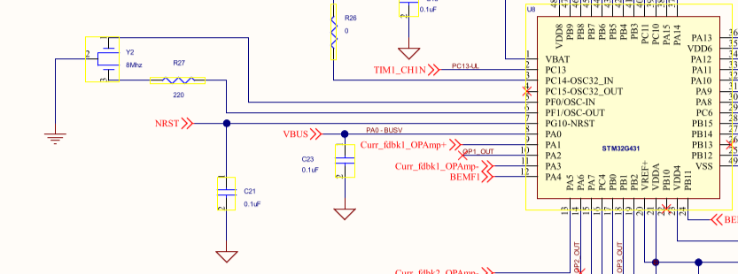
Looking at the schematic for the ESC1, it looks like it has an 8MHz oscillator and not a 16 MHz, but either way I haven’t been able to get to the timing values that work for it using the bit timing calculator linked below, so I think I’m still missing something. E.g. Is the sample-point defined by the transceiver or is it a parameter that’s chosen for a given application?
If you have any resources for learning more about this it’d be appreciated. So far I’ve been using this calculator and reading through some of the information on the same site: http://www.bittiming.can-wiki.info/
Not sure if this gives you different results, but this is the calculator I used that gave me working bit timings: Bit Timing Calculator for CAN FD
What transceiver are you using on your board?
Also, you are using generic G431CBUx define in PIO- are you also using a custom clock.c with correct / updated values? Like you said, the default is set up for 24MHz
1 Like
Pretty sure the bad timings are user error.  This is my first foray into clock timings and the closest I’ve gotten to the bare metal of μc’s, so there’s still a lot I don’t understand.
Do you know where I can find an example of how to use the clock.c? I’ve never messed with that and hadn’t known of it before you mentioned it. For me the #define’s & clock/peripheral configurations have lived in the murky black magic of the stm platform files until very recently, and frankly I still avoid them if possible.
Edit: I’m also using the Adafruit CAN Pal, which is a breakout for the TJA1051/T3. The Picos on the same bus are also using it to talk to the ESC1 during testing.
There actually is nothing special about clock.c, it doesn’t even need to be names this- I think I took it from some repo @runger made. The important thing is that you make sure the function is compiled as C (what extern C does, and that the function has the name SystemClock_Config(void), it is a weak function in the HAL so when the MCU boots up, it uses the internal HSI oscillator, then it looks for this function, and if it finds it, it will run it and update the clock to whatever config is specified.
Here is an example: lemon-pepper-stepper/firmware/src/clock.c at main · VIPQualityPost/lemon-pepper-stepper · GitHub
It is actually not that complicated. If you set up the clock tree using CubeMX, this is the function that is auto-generated if you generate code in main.c that it makes, you can just copy it out into a new file in your PIO project.
I also use the TJA1051 in my board, but I used 12MHz HSE so my timings so the parameters I used (in lib/can folder of that repo) won’t be any good for you, I think.
1 Like
Same for me… to be honest, using FDCAN was the first time I looked into this low level peripheral stuff, because there is so little info on this on the internet, most of the results of searching for using FDCAN with Arduino/ stm32duino are on this forum  (and mostly from @Owen_Williams at that
  )
)
I forgot to mention, sometimes those calculators will give you timing values which are not achievable with the hardware- there are notes in the reference manual (RM0440 for G4) about valid values- some can go 0-31, others only 0-15, so you may need to try and tinker with the calculator to get “real” timing parameters that can actually be loaded on the chip.
1 Like
If you don’t define your own clock.c, then here is where stm32duino is pulling it for genericSTM32G431CBUx, it seems to expect the same HSE and configuration as if you are using a Nucleo: Arduino_Core_STM32/variants/STM32G4xx/G431C(6-8-B)U_G441CBU/generic_clock.c at main · stm32duino/Arduino_Core_STM32 · GitHub
1 Like
I would not start fiddling with the FDCAN bit timings at this stage. No matter if they are right or wrong, you must see something on the Tx pin if you just bluntly try to send (and have the line properly terminated on the bus). If that’s not the case, there is still something totally wrong. Just note that after some failed attempts the CAN bus controller might just shut down and go to an error state, so try to measure right after starting your test program (or even better before). The timing should be corrected by fixing the clock settings of the MCU and not the CAN controller’s bit timings. I used the SystemClock_Config(void) of the generic version without any other clock related defines for my board with the 16MHz crystal. I am sure this is wrong, but CAN bus worked, so you should be able to achieve the same.
1 Like
@VIPQualityPost I think, you originally created the default clock config for the generic variant, right? Is it possible that it runs entirely on the internal clock and disregards the external clock? This also seems to be the case for the B-G431B-ESC1.
1 Like
No, I just added support for it in PlatformIO (adding the board description json- the stm32duino files are automatically generated and already existed, including clock config).
I will try to follow up on your other thread when I get home 
1 Like
I did not want to hijack this thread, hence the new one…