After a bunch of messing around with system clocks and such I’ve gotten to testing in external loopback mode, and that works. Does that mean that the CAN peripheral configuration should be correct, and whatever is going on that’s preventing comms is between the MCU pins and the transceiver pins?
- Edit: just to clarify, still no activity from the misbehaving board at the transceiver outputs. I’ll need to take another look at the mcu pins to make sure there’s no activity there either
Until the scope I ordered recently comes in I’m just working with a cheap logic analyzer so I’m probably going to go back to make sure I didn’t miss anything when looking at the connection between the MCU and transceiver until I have something better to measure. It’d be funny if I got into the weeds this far and it was a simple connection problem, but at least I’ve learned some things 
1 Like
Well, if it doesn‘t take too long, then I would wait for the scope. It is simply so much easier with the right tools and if you can trigger on short pulses. Anyway, if there is absolutely no signal and you configured the correct pins for CAN, then it is most likely a hardware problem. You can also leave the CAN stuff aside and use the pin as GPIO to perform some simple connectivity tests.
1 Like
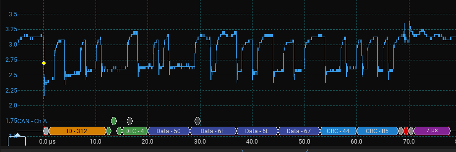
It does look like there’s a hardware problem… For some reason the signal at the RX of the transceiver only drops from 3v3 to 2.5V or so instead of 0V. No idea why it could be doing that since its the same transceiver running at the same voltage as two other devices on the bus I’m testing with.
Edit: this was with a freshly replaced transceiver since I was worried the last one may have been bad… maybe the problem is in the adapter board I made?
So, the scope arrived, excellent! Is the signal above really measured on the Rx pin? The signal looks more like the CAN bus between H and L.
Yeah, can is a differential line so that looks perfect to me if you are measuring one of the two lines w.r.t. GND. What about using one line as a virtual ground to get the signal on the other? I mean, the terminal resistor is probably a little off because the leading edge signal is a little smoothed over but you can tune it. What is the terminal resistor value, and what is the can speed? I’m speculating since there is not actual picture or schematics, I could be totally wrong of course here.
If you mean to put the ground clip on the other differential line, this does not work because the probe is earth referenced through the oscilloscope via shield of the probe (if you had a differential probe, then you can do that). What you can do, however, is measure each signal referenced to ground, and then subtract them on a math channel (most digital oscilloscopes will have this). But like @Grizzly mentions, you probably mean to be looking at CAN RX/TX, not CANH/L. The transceiver needs to adjust the DC levels for whatever the common mode on the bus is, it has a number of jobs- I think you only need to be as concerned about getting a valid signal out of the micro, on CAN Tx/Rx.
Does sigrok have a CAN/FDCAN decoder? That would be a nice way to see what’s going on…
It does and without it my lib would probably not exist  !
!
Yes, that is really measured on the RX pin. Very strange… it’s more difficult to trigger on the RX pin than on the actual CAN L/H lines due to the small voltage drop. It’s only doing this on the one board, the two pi picos on the bus are using the same transceiver but don’t have this issue and do the full 3.3->0 drop instead of just to ~2.6V.
Edit: One thing I did notice is the 3v3 line is pretty noisy, with consistent ripples between 3.35 and 3v, with more intermittent drops to 2.8v. Could that indicate power issues?
The scope software I have includes a decoder, and they for the most part look the same as what I’m seeing on my logic analyzer on the H/L lines, and matches what the other boards on the bus are seeing.
1 Like
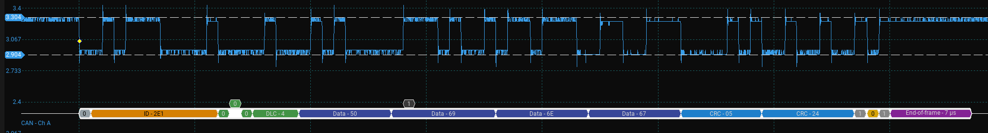
The noise on the 3v3 line was eliminated once I connected the transceiver grounds together - Once I fixed the common ground, the apparent fluctuations on the 3v3 line completely went away.
Here is a better screenshot of a valid CAN frame that was received successfully by other boards on the bus. Unfortunately the small voltage drop on received frames was unchanged, though the signal was much less noisy. Also still nothing seen on the MCU either.
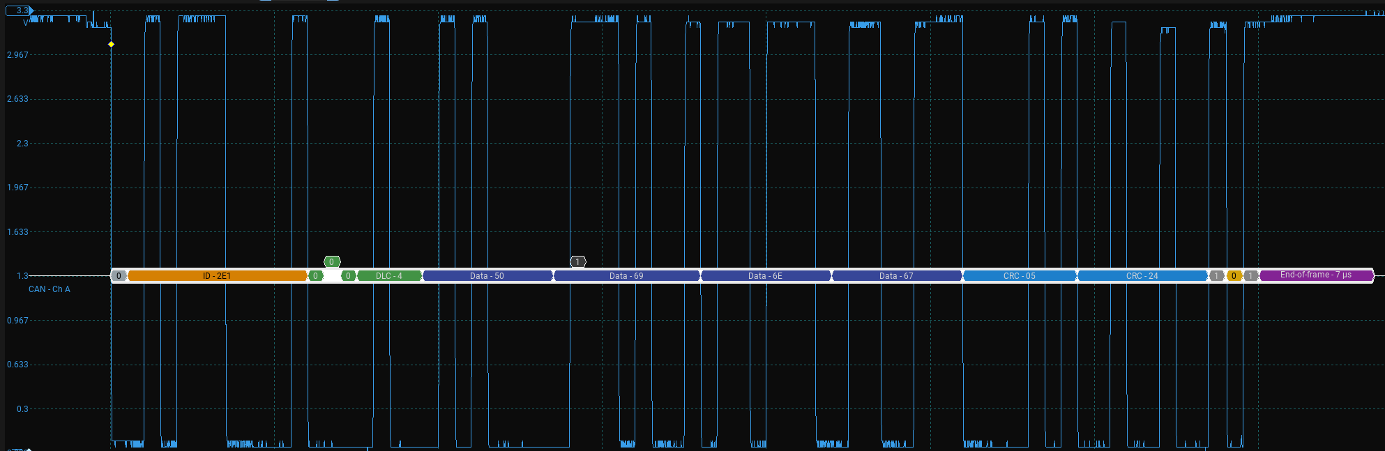
Here is what a message with the same data looks like on another (identical) transceiver on a working device, also reading on the RX pin of the transceiver.
If the first chart (with the small high/low difference) was measured on the Rx pin, it is definitely wrong. The second looks perfect. To make things simpler, I would start with the single, suspect device and a simple resistor as termination for the bus. No other devices. Then, send something and measure Tx, bus and Rx pin. You should see something similar to the above charts (but perhaps only once if there is no device to aknowledge). On the bus the situation should be similar, but with different levels and the Rx pin finally should reflect what you have sent. If that is ok, then attache one (and only one) more device and take it from there. Devide and conquer is the concept here… On a side note: If you use multiple devices, you must make sure that two devices are never ever sending the same CAN ID at the same time since this will mess with the bus arbitration (I had that problem recently with the example that comes with my lib…).
1 Like
More bulk capacitance?
I’m speaking out of my butt here, since I cant see your setup.
Cheers,
Valentine
1 Like
Not quite there yet, but the CAN breakout I currently have soldered and the previous one put out good signals on RX for a few seconds before degrading to the problematic signals… maybe the charge pump on those boards is acting up or I somehow damaged them? Hopefully I’ll find out this weekend
Now I’m more confused… I took a working transceiver and swapped it with the one in the adapter board and the problem stayed with the adapter board and the transceiver previously on the adapter board also functioned fine when swapped onto a pico. The transceiver newly on the adapter board had the exact same behavior as the last one, even down to having the full voltage drop for a few transmissions and then going back to that tiny .3v drop.
Maybe that’s a sign of the STM CAN peripheral erroring out… does anyone know of status bits I can check to see if that’s the case, or a good resource for STM CAN configuration / debugging?
Well I found it after debugging line by line with a scope… turns out I sent an older version of my adapter board to the PCB fab than I thought and sent something with RX and TX crossed. CAN receiving and sending works as expected now. At least I’ve learned some things and have a scope now 
Thanks for the help everyone!
3 Likes
Congratulations!!! Great to see success here!
1 Like
At the end, this is all what such hobbies are about!
3 Likes