What’s the X * Y size of this in mm? Thanks
50*50mm , standard 1.6mm 2 layer design.
Stitching vias 0.5mm/0.3mm
Current vias 100mil/50mil
Battery track width 240 mil
When designing a motor driver, you need to consider the return current path, from the source pin of the MOSFET to the GND of the input connector. In your design that path is too thin.
Also consider the path from the source pin to the output. That path also looks a little thin.
Your schematic is wrong around the gate driver chip, the bootstrapping circuit is not set up correctly. Refer to the datasheet for the correct circuit.
Consider using a 4 layer or 6 layer PCB, so you can add power and ground planes on the inner layers.
Also reconsider your choice of MOSFET, your one currently has a resistance of 23 milliohms, which is a bit high if you are targeting 15A. If we assume worst case, we have 15 amps in each phase, the total power losses will be around 15W, which means you need a heatsink. If you are able to get MOSFETs with a low on resistance (3 milliohm MOSFETs can be obtained for under $1USD each), you will reduce power losses significantly and won’t need a heatsink.
Regarding gate resistors, it is hard to say exactly what value you should use, but you should use the lowest value that does not cause any voltage overshoot or ringing. I suggest buying multiple resistor values between 1 ohm and 47 ohms, and using an oscilloscope to check for ringing and overshoot for each resistor value, and picking the most suitable one.
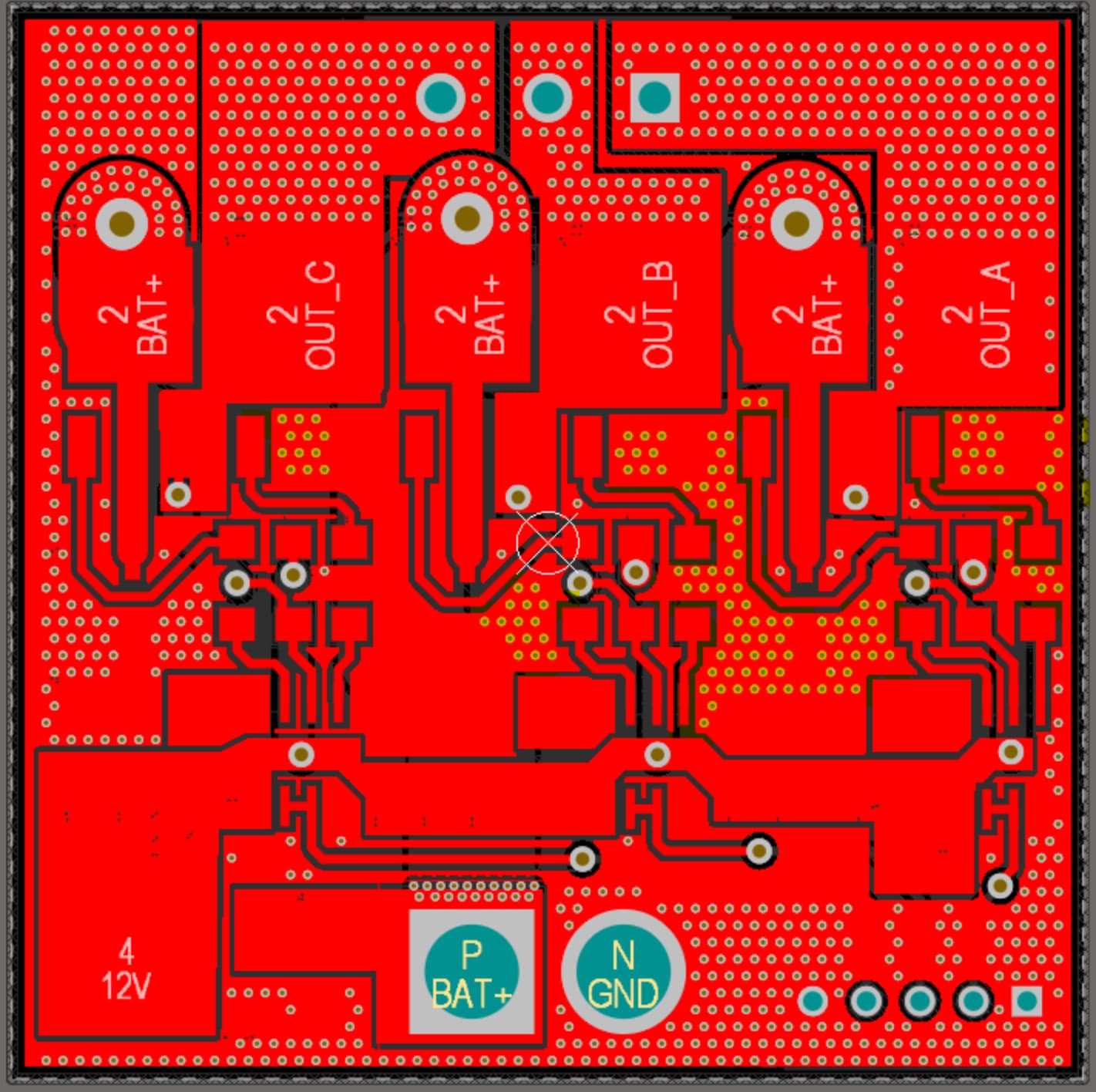
Return paths in the design are completely stitching vias based, I don’t see any singular (thin) track in my design.
Can you please highlight the path you’re referring to?
The source power is also sent via 240 mil track with proper stitching at extreme source(battery connector) and near each mosfet gate. Please highlight the part of design that seems to have thinner tracks for source.
Noted the observations about mosfets, do you recommend any specific MOSFET that satisfies the required Rds?
Noted the observations about gate driver circuit, will verify the same from datasheet.
Regarding layer count, currently my aim to implement closed loop control without ANY firmware issues on the setup. Will move to a MCU integrated 6 layer design once the above driver circuitry is validated.
I’ve highlighted the stitching vias in the top layer which carry the return current from the MOSFETs.
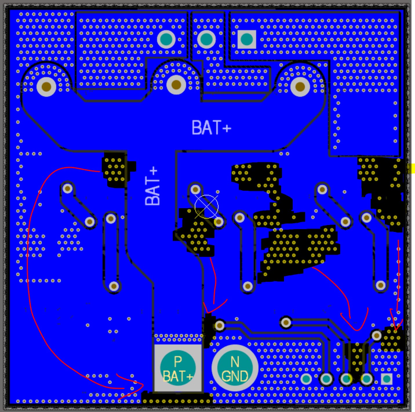
I’ve also drawn the path of the return current on the bottom layer and highlighted the thin parts.
I am using the BSZ0901NS in my design. It costs $1 USD for a quantity of 1 at Mouser, and is also available for $0.78 at LCSC. An alternative is the CSD17575Q3 which costs $0.74 USD at Mouser. There are many other alternatives, you just need to look harder. Both of these MOSFETs have under 2 milliohm RDSon at room temperature, the RDSon will increase as they heat up, but they will never exceed 4 milliohms.
Regarding your plans to implement closed loop control, you are missing current sensing hardware. Due to the analog circuitry required, it is highly recommended to have everything on the same PCB to reduce trace lengths and noise.
You can have a look at my design in a previous post if you want a reference design. I haven’t produced the boards yet, but I’m 90% confident it will work properly. It uses the DRV8323 which is a “smart gate driver”, which means the gate resistors are integrated and software configurable, so you won’t need external ones. It is optimized for high performance and uses RDSon current sensing for the lowest power losses, however the trade off is reduced accuracy compared to resistor sensing (which is the recommended way to do it). It also uses tantalum capacitors which are really expensive, and you should swap them out for electrolytics if you want a low cost design.
Your design also has CAN, really useful for my application as well.
Can you please share the timeline, by when are you expecting your boards?
Everything you mentioned seems to be available on Mouser in large quantities, I’ll reconsider my design and switch to a “smart” one based on your design reference.
Thanks for the help ![]()
Please let me know if you require any iterations on your design, I’ll be happy to work on it along with you.
I am waiting for JLCPCB to restock the MR30PW connector which is the motor connector. After that I will order the boards with SMT assembly by JLCPCB. I expect to get the boards in around 3 weeks. I would prefer to make them myself but the connectors have huge heat sink pads attached to them meaning professional wave soldering is going to result in a much better solder joint.
If you’d prefer we can work together on my design, I would really appreciate someone else to look over it because sometimes I miss some silly mistakes. I plan to open source the design once I am done.
However be mindful that my design is NOT fully compatible with SimpleFOC due to the extreme timing requirements of reading the current, and also SimpleFOC does not support temperature compensated lowside current sensing yet. It should still work with SimpleFOC but with reduced performance (lower switching frequency to relax timing requirements and lower current so the MOSFETs not heat up)
1 Like
Okay noted.
I’m not a firmware expert, hence am looking for something that is stock supported by SimpleFOC.
Does adding extra circuitry for current sense solve the above mentioned firmware issues in your design?
Yes, you just need to use the resistor sense method. Then it will be fully compatible with SimpleFOC. Alternatively you can just live with lower current (10A). This way the MOSFETs will not heat up, and the current sense will still be accurate enough, and it will also be compatible with SimpleFOC given you use a lower switching frequency (25KHz) to relax timing requirements.
I should probably mention that if you use the DRV8323 you will have to write firmware which communicates with the driver to set all the settings, such as CSA gain, PWM mode, gate resistor value (gate drive current), etc. This is not provided with SimpleFOC so you will have to do this yourself.
From what I understand,
Usage of smart gate driver like DRV83xx will help me avoid the gate resistor selection routine and provide with some protection. However the firmware will get a bit complicated for me.
I can go ahead with corrections in my design itself with addition of MCU and current sense setup. Will that suffice or you suggest any more additions in my original design?
A smart gate driver will only provide protection if the settings are configured correctly, it is not as foolproof as an Integrated FET driver. It is up to you what other features you want in your design and it is not something I can decide.
My suggestions are to
- fix the small traces
- decide to fix your current gate driver circuit or switch to DRV8323 if you like it better
- add current sense and MCU on the PCB
- switch MOSFET to lower resistance one
- use 4 or 6 layer PCB
If you want, you can make a copy of my design and start from there, it could save you some effort.
Hi Andrew, I have fixed the bootstrapping error in my current design.
- Noted the routing issues, will get to fixing those once Schematic is in place.
- I will proceed with Integrated FET design, will add current sensing to my existing design.
- Will host Stm32F4 (Blackpill) on the PCB for now, will shift to bare IC after POC
- In search of lower resistance mosfets, The one in design are the ones in my inventory, hence will proceed with them to check POC
- Noted, will switch to a 4/6 layer stack once schematic is finalised.
For Current sensing, is Arduino-SimpleFOC-PowerShield a good place to start?
Hi Anirudha,
Do you want to continue with an integrated FET design or a discrete FET design? I am not sure why you would need lower resistance MOSFETs if you want to proceed with the integrated FET design. Or are you planning to start with integrated and move to discrete later?
The SimpleFOC PowerShield you linked is not a good place to start, it uses half bridges with integrated drivers but those are really old and they have extremely long switching times, meaning you won’t get good performance and it will heat up due to switching loss and you can’t run high PWM frequency which limits maximum motor speed. It is also not foolproof, because the overcurrent protection threshold seems to be set at 60 amps, which is way too high.
If you would like to start with an integrated FET design, you can check out my previous motor driver based off the DRV8316 https://easyeda.com/editor#id=|99132368fc384463a48528e5faa7b4ee|19356f95894c45c1ad31805f8862b7ef (copy and paste, clicking doesn’t work). I have already produced these boards and can guarantee it works with my custom firmware, but I haven’t validated SimpleFOC on them. It is an 8 layer design due to a special offer from JLCPCB but you can remove 3 internal GND planes and the internal VCC plane to make it 4 layers.
Just remember with an integrated FET design you won’t get much current, as the MOSFETs in the DRV8316 are 50 milliohms, I am able to get 8A (Peak, 5.6A RMS) for 1 second and 5A (Peak, 3.5A RMS) for at least 2 minutes before overheating.
My apologies, I meant Discrete FET design. For me the task currently is to understand working of SimpleFOC and start using BLDCs in my existing workflow.
Noted that the Powershield current sensing seems to be handled by the BTN drivers as well, through the Is pin.
From a quick search the most readily available and easier for me to integrate is ACS712 based approach. https://community.simplefoc.com/t/asc712-current-sensors/1948/5
Above thread explains how to add it in my setup, Is there anything I should be aware of before implementing above explaination?
The ASC712 is an isolated hall effect current sensor with 80KHz bandwidth. It is probably the easiest way to get started with current sensing. Just be aware it is usually used as an inline current sensor which makes the software side easier, and if you are considering low side current sensing in the future (usually cheaper to implement) then you will need to plan for it now as there are some timing requirements to be aware of (which most likely are handled by SimpleFOC).
Understood, I’ll implement ACS712 in my design.
Will share schematics once I’m done adding current sense part along with the MCU.
Thanks a ton
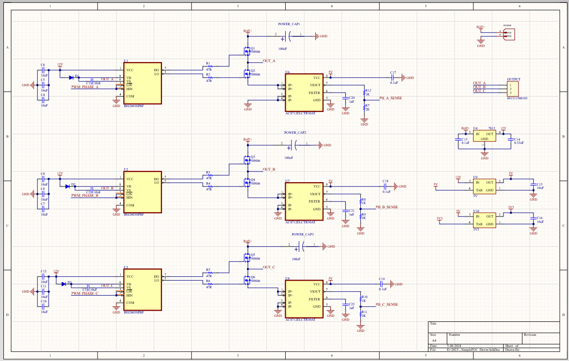
Implemented ACS712 in the existing design. Currently sticking to a voltage divider to translate the 5V adc to 3.3V.
Corrected the bootstrapping error.
Please review if I have missed anything. Routing this will be fun ![]()
Your resistor values for the voltage divider on the output of the ACS712 are too low, they should be increased so the total is at least 4.7kohm.
I suggest using a 10k and 20k resistor in place of your 1k and 2k resistor.
Other than that it looks fine
1 Like