Yes, I saw it ![]()
Ah Chinese and colors …
Hello
I have just tested different modes with MKS DRIVE MINI + AS5047P + iPower GM5208-24
foc_current & velocity ==> OK ==> 34 Rad/s max
foc_current & torque ==> OK
foc_current & angle ==> OK
Then I tested voltage & velocity mode
The motor runs irradiently and vibrates horribly?
I change the value of:
motor.LPF_velocity.Tf = 0.01f; // defaut 0.005
To:
motor.LPF_velocity.Tf = 1.0f; // defaut 0.005
and it’s OK ==> 37 Rad/s max at 20v
I forgot the GPIO cable at the fablab, without it it’s difficult to debug because there’s no serial port, I’ll test it on Monday…
i have just St-Link V2 for debug
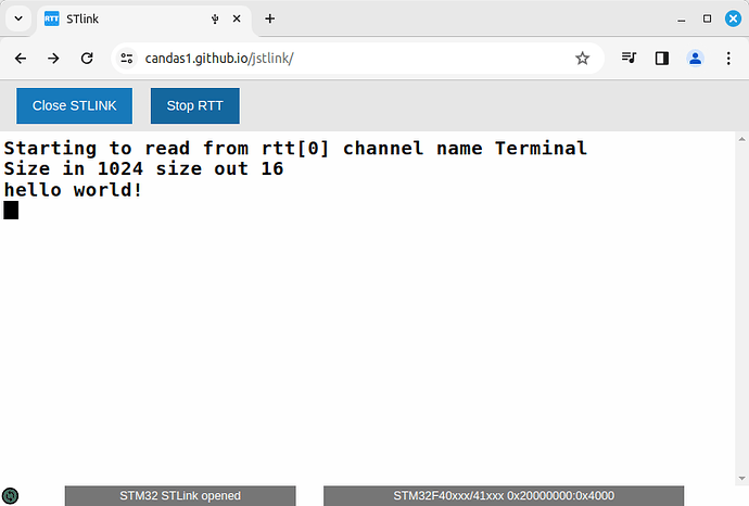
This is one way to get the output without serial.
But I use it only in platformio, I cannot comment about Arduino IDE.
[EDIT] If you are using a chinese clone, you can try my fork that is simplified and adapted to stlink v2.1
This value is much too high… The system may be stable at a constant velocity, but it will be very unreactive to load changes. I can’t imagine it will work well like this…
My tests in these modes
foc_current & velocity ==> OK ==> 34 Rad/s max
foc_current & torque ==> OK
foc_current & angle ==> OK
work with values between 0.01f; <=&=> 0.005
But when I switched to voltage & velocity mode
the engine vibrated loudly and wouldn’t turn…
After searching for the right P.I.D. values
I finally increased it to 1.0 motor.LPF_velocity.Tf
and that’s when the motor started to run well???
And if I lower it, it locks up and starts vibrating again ???
I would check the other PID values - when you switch from torque-current to velocity mode, the other PID values may need to be changed. The motor.LPF_velocity.Tf you can tune it to use values between 0.001 and 0.1 maybe, but I would not go higher than this.
You can check the effect if you try to hold the motor - it will probably behave very strangely with a LPF of 1.0.
Voltage mode should be fairly easy to tune - you don’t need any PID values for it. The LPF value is still used though. If you find that you need to set the LPF to 1.0 in voltage mode, then I think you should check your sensor values. My suspicion would be that you are getting some bad values now and then, maybe due to electrical noise. A high filter value will suppress these bad values, but at the expense of control bandwidth. A better solution (if I am right in my assumption) would be to solve the sensor noise problems.
@runger & @Candas1
You’re right, with TF at 1.0 it runs smoothly, but if I try to change gear, everything goes to hell…
Well I don’t understand in openloop everything works.
in closed loop DC current velocity|angle|torque OK
in closed loop FOC current velocity|angle|torque OK
And in closed loop no way to make Voltage work correctly …
I added an M5StickC in serial connection to gpio 3 and 4 to get simpleFOCStudio,
and no better impossible to make the voltage mode work properly in closed loop …
Are you using the Phase_resistance, kv or phase_inductance parameters?
At the moment I have this in my settings:
  motor.velocity_limit = 30.0f; // [rad/s]
  motor.voltage_limit = 0.5f * driver.voltage_limit; // [Volts] // Calcul ==> 5.57[Ohms]*1.0[Amps]=5,57[Volts] // [V] - if phase resistance not defined
  motor.current_limit = 0.95f; // Current limit [Amps] - if phase resistance defined
  motor.phase_resistance = 25.6f; // [Ohms]  // motor phase resistance // I_max = V_dc/R
  //motor.KV_rating = 43; // [rpm/Volt] - default not set // motor KV rating [rpm/V]
  // commenter les 2 ci-dessous pour avoir le test au demarrage
  //motor.zero_electric_angle = 0.11f; // zero_electric_angle
  //motor.sensor_direction = Direction::CW; // Cw/CCW // direction
EDIT:
Hummm
you need to comment phase_resistance for voltage mode,
this is my mistake?
To be honest I don’t like the current estimation, I don’t use phase resistance with voltage mode.
It could be part of the problem… if you specify the phase resistance, you don’t get voltage control but rather “estimated current” control. In this mode, the PID values generally need to be set 10x lower than in voltage mode.
So using the same PID values as in current control mode probably won’t work well.
You can remove the phase resistance for only voltage control, then the PID values are 10x higher, approximately.
Note that this is for velocity mode… in torque mode, this PID is not used.
Thanks for your answers, it’s clearer for me now.
The two modes I’m interested in on the motor/controller pair I’m testing work well,
so I’m going to fine-tune them and forget the voltage mode
I don’t know if it would be confusing for people, but it could be useful to have a estimated_current mode as opposed to foc_current mode, so people could switch between voltage and estimated_current without having to comment phase_resistance.
During my tests with sensorless, I needed the phase_resistance for the flux observer but didn’t want estimated current in voltage mode.
This mode could have it’s own PID parameters for velocity.
Hello,
A short video of my latest test of the “MKS DRIVE MINI” board with an iPower GM5208-24 motor in angle & foc_current mode with optimized P.I.Ds.
A serial connection via GPIO with an M5StickCPlus2 allows me to control the unit via Bluetooth.
I think the “MKS DRIVE MINI” card is a really good solution for us, especially if it stays at this price.
SimpleFOC_MKS_DRIVE_MINI_V2.zip
https://sourceforge.net/projects/openhardware-eu/files/SimpleFOC_MKS_DRIVE_MINI/
Looks like it is back at 35e
Can anyone share photo of the XDRIVE mini PCB backside?
Hello,
I didn’t think to take any photos when I dismantled the radiator,
I only have 1 photo under the microscope of the AS5047P part.
@Candas1 may have more photos to hand …
Download photos:
Phohos ODriLi3.6 + AS5047P.zip
https://sourceforge.net/projects/openhardware-eu/files/ODESC%204.2%20board%20AS5047P%20%2B%20GM5208-24/
Just want to check how they rerouted it around the encoder.


