Yes we were discussing it with @Antun_Skuric earlier today, please don’t use dev branch for now.
Huh huh, you’re using low-side current sensing right? ![]()
Yes
/*
SimpleFOC_STM32F405RGT6
odrive 3.6 - odesk 4.2
Hall sensor example code
This is a code intended to test the hall sensors connections and to demonstrate the hall sensor setup.
odrive_example_encoder.ino
https://github.com/simplefoc/Arduino-FOC/blob/dev/examples/hardware_specific_examples/Odrive_examples/odrive_example_encoder/odrive_example_encoder.ino
https://community.simplefoc.com/t/problems-with-custom-firmware-for-odrive-v3-5-using-simplefoc/2743
#include <Arduino.h>
#include <Wire.h>
https://github.com/simplefoc/Arduino-FOC/tree/master/examples/hardware_specific_examples/Odrive_examples
SoftwareSerial STM32F405RGT6
ODrive-fw-v0.5.6
https://github.com/odriverobotics/ODrive/releases
https://docs.odriverobotics.com/v/0.5.6/getting-started.html
Anti Spark Switch
IRFS7530TRL7PP
https://github.com/msglazer/Anti-Spark_Switch
*/
#include <Arduino.h>
#include <SimpleFOC.h>
#include <SimpleFOCDrivers.h>
#include <encoders/smoothing/SmoothingSensor.h>
//#define SIMPLEFOC_DISABLE_DEBUG
/*-D SIMPLEFOC_DISABLE_DEBUG*/
//M0
#define A_HALL1 PB4
#define A_HALL2 PB5
#define A_HALL3 PC9
//M0
#define M0_IA _NC // Pas dispo en A !
#define M0_IB PC0
#define M0_IC PC1
// Odrive M0 motor pinout
#define M0_INH_A PA8
#define M0_INH_B PA9
#define M0_INH_C PA10
#define M0_INL_A PB13
#define M0_INL_B PB14
#define M0_INL_C PB15
// M1 & M2 common enable pin
#define EN_GATE PB12
//Pole pair
#define PP 10
//Temp
#define M0_TEMP PC5
// Motor instance
BLDCMotor motor = BLDCMotor(PP);
BLDCDriver6PWM driver = BLDCDriver6PWM(M0_INH_A, M0_INL_A, M0_INH_B, M0_INL_B, M0_INH_C, M0_INL_C, EN_GATE);
// low side current sensing define
// 0.0005 Ohm resistor
// gain of 10x
// current sensing on B and C phases, phase A not connected
//LowsideCurrentSense currentSense = LowsideCurrentSense(0.0005f, 10.0f, M0_IA, M0_IB, M0_IC);
LowsideCurrentSense currentSense = LowsideCurrentSense(0.0005f, 30.0f, M0_IA, M0_IB, M0_IC);
//▬▬▬▬▬▬▬▬▬▬▬▬▬▬▬▬▬▬▬▬▬▬▬▬▬▬▬▬▬▬▬▬▬▬▬▬▬▬▬▬▬▬▬▬▬▬▬▬▬▬Hall▬▬▬▬▬▬▬▬▬▬▬▬▬▬▬▬▬▬▬▬▬▬▬▬▬▬▬▬▬▬▬▬▬▬▬▬▬▬▬▬▬▬▬▬▬▬▬▬▬▬
// Hall sensor instance
// HallSensor(int hallA, int hallB , int cpr, int index)
// - hallA, hallB, hallC - HallSensor A, B and C pins
// - pp - pole pairs
HallSensor sensor = HallSensor(A_HALL1, A_HALL2, A_HALL3, PP); // PP = xx aimants / 2 = pole pair
// Interrupt routine intialisation
// channel A and B callbacks
void doA() {
sensor.handleA();
}
void doB() {
sensor.handleB();
}
void doC() {
sensor.handleC();
}
//▬▬▬▬▬▬▬▬▬▬▬▬▬▬▬▬▬▬▬▬▬▬▬▬▬▬▬▬▬▬▬▬▬▬▬▬▬▬▬▬▬▬▬▬▬▬▬▬▬▬SPI▬▬▬▬▬▬▬▬▬▬▬▬▬▬▬▬▬▬▬▬▬▬▬▬▬▬▬▬▬▬▬▬▬▬▬▬▬▬▬▬▬▬▬▬▬▬▬▬▬▬
/*
// SPI
#define SPI_MOSI PC11
#define SPI_MISO PC12
#define SPI_SCK PC10
#define M1_nCS PC14
*/
//▬▬▬▬▬▬▬▬▬▬▬▬▬▬▬▬▬▬▬▬▬▬▬▬▬▬▬▬▬▬▬▬▬▬▬▬▬▬▬▬▬▬▬▬▬▬▬▬▬▬HardwareSerial_Serial1▬▬▬▬▬▬▬▬▬▬▬▬▬▬▬▬▬▬▬▬▬▬▬▬▬▬▬▬▬▬▬▬▬▬▬▬▬▬▬▬▬▬▬▬▬▬▬▬▬▬
#define PIN_SERIAL1_RX PA3
#define PIN_SERIAL1_TX PA2
#define SERIAL_PORT_HARDWARE Serial1
HardwareSerial Serial1(PIN_SERIAL1_RX, PIN_SERIAL1_TX); // RX, TX
//▬▬▬▬▬▬▬▬▬▬▬▬▬▬▬▬▬▬▬▬▬▬▬▬▬▬▬▬▬▬▬▬▬▬▬▬▬▬▬▬▬▬▬▬▬▬▬▬▬▬USB_OTG_Serial▬▬▬▬▬▬▬▬▬▬▬▬▬▬▬▬▬▬▬▬▬▬▬▬▬▬▬▬▬▬▬▬▬▬▬▬▬▬▬▬▬▬▬▬▬▬▬▬▬▬
// https://www.stm32duino.com/viewtopic.php?p=12540&hilit=USBD_VID#p12540
/*
USB OTG
USB_P ==> PA12 USART1_RTS USB_P
USB_N ==> PA11 USART1_CTS USB_N
-D PIO_FRAMEWORK_ARDUINO_ENABLE_CDC
;-D PIO_FRAMEWORK_ARDUINO_USB_LOWSPEED_FULLMODE ;This is not needed anymore, more in documentations.
-D USBCON
-D USBD_VID=0x0483
-D USBD_PID=0x5740
-D USB_MANUFACTURER="SimpleFOC"
-D USB_PRODUCT="\"SimpleFOC_STM32F405RGT6\""
-D HAL_PCD_MODULE_ENABLED
// https://github.com/stm32duino/Arduino_Core_STM32/blob/main/cores/arduino/WSerial.h
-DSERIAL_UART_INSTANCE=1
-D HAL_OPAMP_MODULE_ENABLED
-DSIMPLEFOC_STM32_DEBUG
-DPIO_FRAMEWORK_ARDUINO_ENABLE_CDC
-DUSBD_USE_CDC
-DUSBCON
*/
#include <HardwareSerial.h>
HardwareSerial SerialUSB(USART1); // Enable USB Serial
//▬▬▬▬▬▬▬▬▬▬▬▬▬▬▬▬▬▬▬▬▬▬▬▬▬▬▬▬▬▬▬▬▬▬▬▬▬▬▬▬▬▬▬▬▬▬▬▬▬▬Commander▬▬▬▬▬▬▬▬▬▬▬▬▬▬▬▬▬▬▬▬▬▬▬▬▬▬▬▬▬▬▬▬▬▬▬▬▬▬▬▬▬▬▬▬▬▬▬▬▬▬
// https://docs.simplefoc.com/communication
// instantiate the commander
Commander command = Commander(Serial1);
// motor SimpleFOCStudio ==> M
void doMotor(char* cmd) {
command.motor(&motor, cmd);
//command.target(&motor, cmd); // ok
//command.motion(&motor, cmd);
}
//▬▬▬▬▬▬▬▬▬▬▬▬▬▬▬▬▬▬▬▬▬▬▬▬▬▬▬▬▬▬▬▬▬▬▬▬▬▬▬▬▬▬▬▬▬▬▬▬▬▬SmoothingSensor▬▬▬▬▬▬▬▬▬▬▬▬▬▬▬▬▬▬▬▬▬▬▬▬▬▬▬▬▬▬▬▬▬▬▬▬▬▬▬▬▬▬▬▬▬▬▬▬▬▬
// wrapper instance SmoothingSensor
// https://github.com/simplefoc/Arduino-FOC-drivers/blob/dev/examples/encoders/smoothing/smoothing.ino
SmoothingSensor smooth(sensor, motor);
int sensorTYPE = 0;
void enableSmoothing(char* cmd) {
motor.linkSensor((Sensor*)&smooth);
sensorTYPE = 0;
}
void enableSensor(char* cmd) {
motor.linkSensor((Sensor*)&sensor);
sensorTYPE = 1;
}
//▬▬▬▬▬▬▬▬▬▬▬▬▬▬▬▬▬▬▬▬▬▬▬▬▬▬▬▬▬▬▬▬▬▬▬▬▬▬▬▬▬▬▬▬▬▬▬▬▬▬AUX▬▬▬▬▬▬▬▬▬▬▬▬▬▬▬▬▬▬▬▬▬▬▬▬▬▬▬▬▬▬▬▬▬▬▬▬▬▬▬▬▬▬▬▬▬▬▬▬▬▬
//AUX_L PB10
//AUX_H PB11
//▬▬▬▬▬▬▬▬▬▬▬▬▬▬▬▬▬▬▬▬▬▬▬▬▬▬▬▬▬▬▬▬▬▬▬▬▬▬▬▬▬▬▬▬▬▬▬▬▬▬readSensor▬▬▬▬▬▬▬▬▬▬▬▬▬▬▬▬▬▬▬▬▬▬▬▬▬▬▬▬▬▬▬▬▬▬▬▬▬▬▬▬▬▬▬▬▬▬▬▬▬▬
// https://github.com/simplefoc/Arduino-FOC/blob/dev/examples/utils/sensor_test/generic_sensor/generic_sensor.ino
// https://github.com/stm32duino/Arduino_Core_STM32/blob/c83db2e4f6b4b8d3bbedce67d2156a58023bc432/variants/STM32F4xx/F405RGT_F415RGT/PeripheralPins.c#L43
#define HAL_ADC_MODULE_ENABLED
// PA_1 // PA_1_ALT1 // PA_1_ALT2
#define PIN_POT1 PA_1_ALT2 // PA1 On utilise
int valPOT;
//▬▬▬▬▬▬▬▬▬▬▬▬▬▬▬▬▬▬▬▬▬▬▬▬▬▬▬▬▬▬▬▬▬▬▬▬▬▬▬▬▬▬▬▬▬▬▬▬▬▬setup▬▬▬▬▬▬▬▬▬▬▬▬▬▬▬▬▬▬▬▬▬▬▬▬▬▬▬▬▬▬▬▬▬▬▬▬▬▬▬▬▬▬▬▬▬▬▬▬▬▬
void setup() {
//▬▬▬▬▬▬▬▬▬▬▬▬sensor_analog▬▬▬▬▬▬▬▬▬▬▬▬
//pinMode(PIN_POT1, INPUT_PULLUP);
pinMode(PIN_POT1, INPUT_ANALOG);
//analogReadResolution(8); // 12
//▬▬▬▬▬▬▬▬▬▬▬▬CAN▬▬▬▬▬▬▬▬▬▬▬▬
//CAN_R PB8
//CAN_D PB9
//▬▬▬▬▬▬▬▬▬▬▬▬AUX▬▬▬▬▬▬▬▬▬▬▬▬
//AUX_L PB10
//AUX_H PB11
//▬▬▬▬▬▬▬▬▬▬▬▬Temp▬▬▬▬▬▬▬▬▬▬▬▬
//pinMode(M0_TEMP, INPUT_PULLUP); // M0_TEMP PC5
//pinMode(AUX_TEMP, INPUT_PULLUP); // AUX_TEMP PA5
//▬▬▬▬▬▬▬▬▬▬▬▬GPIO1/GPIO2/GPIO3/GPIO4▬▬▬▬▬▬▬▬▬▬▬▬
//pinMode(PA0, OUTPUT); // GPIO1 ADC123_IN0 UART4_TX
//digitalWrite(PA0, LOW); // HIGH/LOW
//pinMode(PA1, OUTPUT); // GPIO2 ADC123_IN1 UART4_RX
//digitalWrite(PA1, LOW); // HIGH/LOW
/*
// PA2 utilisé pour RX/TX avec SoftwareSerial
//pinMode(PA2, OUTPUT); // GPIO3 ADC123_IN2 USART2_TX
//digitalWrite(PA2, LOW); // HIGH/LOW
// PA3 utilisé pour RX/TX avec SoftwareSerial
//pinMode(PA3, OUTPUT); // GPIO4 ADC123_IN3 USART2_RX
//digitalWrite(PA3, LOW); // HIGH/LOW
*/
//▬▬▬▬▬▬▬▬▬▬▬▬HardwareSerial_Serial1▬▬▬▬▬▬▬▬▬▬▬▬
pinMode(PIN_SERIAL1_RX, INPUT_PULLUP); // sur GPIO4 ==> PA3
pinMode(PIN_SERIAL1_TX, OUTPUT); // sur GPIO3 ==> PA2
Serial1.begin(921600); // 921600 115200 230400
_delay(1000);
//▬▬▬▬▬▬▬▬▬▬▬▬USB_OTG_Serial▬▬▬▬▬▬▬▬▬▬▬▬
SerialUSB.begin(115200);
//▬▬▬▬▬▬▬▬▬▬▬▬driver▬▬▬▬▬▬▬▬▬▬▬▬
// pwm frequency to be used [Hz]
driver.pwm_frequency = 20000; // 20000 max STM32
driver.voltage_power_supply = 24.0f; // power supply voltage [V]
driver.voltage_limit = 20.0f; // Max DC voltage allowed - default voltage_power_supply
/*
https://docs.simplefoc.com/bldcdriver6pwm
Le paramètre de la zone morte est défini comme la quantité du cycle de service qui est réservée
entre les changements du mosfet actif. Chaque fois que le côté haut/bas est désactivé
et que le côté bas/haut est activé, la moitié de la zone morte est injectée.
Ce paramètre est équivalent au temps mort,
le temps mort peut être calculé comme suit : dead_time = 1/pwm_frequency*dead_zone
*/
// 1/20000*dead_zone=?
driver.dead_zone = 0.05f; // dead_zone [0,1] - default 0.02f - 2%
driver.init();// driver init
motor.linkDriver(&driver); // link the motor and the driver
//▬▬▬▬▬▬▬▬▬▬▬▬Current▬▬▬▬▬▬▬▬▬▬▬▬
// https://docs.simplefoc.com/low_side_current_sense
currentSense.linkDriver(&driver); // link the driver
//▬▬▬▬▬▬▬▬▬▬▬▬HALL sensor▬▬▬▬▬▬▬▬▬▬▬▬
sensor.pullup = Pullup::USE_EXTERN; // check if you need internal pullups
sensor.init(); // initialise encoder hardware
sensor.enableInterrupts(doA, doB, doC); // hardware interrupt enable
motor.linkSensor(&sensor); //
// SmoothingSensor
// https://github.com/simplefoc/Arduino-FOC-drivers/blob/dev/examples/encoders/smoothing/smoothing.ino
smooth.phase_correction = -_PI_6; // set SmoothingSensor phase correction for hall sensors
//motor.linkSensor(&smooth);// link the SmoothingSensor to the motor
_delay(1000);
//▬▬▬▬▬▬▬▬▬▬▬▬mode▬▬▬▬▬▬▬▬▬▬▬▬
// set torque mode
// https://docs.simplefoc.com/foc_current_torque_mode
motor.torque_controller = TorqueControlType::foc_current; // foc_current || dc_current || voltage
motor.controller = MotionControlType::velocity; // angle velocity torque // Control loop type
// choose FOC modulation
// FOCModulationType::SinePWM; (default)
// FOCModulationType::SpaceVectorPWM;
// FOCModulationType::Trapezoid_120;
// FOCModulationType::Trapezoid_150;
motor.foc_modulation = FOCModulationType::SinePWM; // pwm modulation settings
motor.modulation_centered = 1; // 1
//▬▬▬▬▬▬▬▬▬▬▬▬ALL_PID▬▬▬▬▬▬▬▬▬▬▬▬
// velocity PID
motor.PID_velocity.P = 0.075f; // 0.08f
motor.PID_velocity.I = 0.8f; // 0.8f
motor.PID_velocity.D = 0.0001; // 0.001f
//motor.PID_velocity.output_ramp = 1000.0f;
//motor.PID_velocity.limit = 5.0f; // ? current_limit [Amps] // https://community.simplefoc.com/t/setting-current-limits-in-main-loop/1972
//motor.LPF_velocity.Tf = 0.001f; //0.01f // Low pass filtering time constant
// angle PID
motor.P_angle.P = 30.0f; // 30.0
//motor.P_angle.I = 0.0f;
//motor.P_angle.D = 0.0f;
//motor.P_angle.output_ramp = 10000.0f; // 10000.0
//motor.P_angle.limit = 120.0f; // ? velocity_limit [rad/s]
//motor.LPF_angle.Tf = 0.001f; // Low pass filtering time constant
// current q PID
motor.PID_current_q.P = 0.05f; // 0.05f
motor.PID_current_q.I = 30.0f; // 50.0f
//motor.PID_current_q.D = 0.001f; //0.001f
//motor.PID_current_q.output_ramp = 1000.0f; //1000.0f
//motor.PID_current_q.limit = 3.0f; // https://community.simplefoc.com/t/setting-current-limits-in-main-loop/1972
//motor.LPF_current_q.Tf = 0.005f; // 0.005f Low pass filtering time constant
// current d PID
motor.PID_current_d.P = 0.05f; // 0.05f
motor.PID_current_d.I = 30.0f; // 50.0f
//motor.PID_current_d.D = 0.001f; //0.001f
//motor.PID_current_d.output_ramp = 1000.0f; //1000.0f
//motor.PID_current_d.limit = 3.0f; // https://community.simplefoc.com/t/setting-current-limits-in-main-loop/1972
//motor.LPF_current_d.Tf = 0.005f; // 0.005f Low pass filtering time constant
//▬▬▬▬▬▬▬▬▬▬▬▬Limits▬▬▬▬▬▬▬▬▬▬▬▬
motor.velocity_limit = 120.0f; // [rad/s] (120[rad/s] ==> ~1200[RPM])
motor.voltage_limit = 0.5f * driver.voltage_limit; // [Volts] // Calcul ==> 5.57[Ohms]*1.0[Amps]=5,57[Volts] // [V] - if phase resistance not defined
// https://www.digikey.fr/fr/resources/conversion-calculators/conversion-calculator-ohms
motor.current_limit = 5.0f; // Current limit [Amps] - if phase resistance defined
//motor.phase_resistance = 0.5f; // [Ohms] // motor phase resistance // I_max = V_dc/R
motor.phase_resistance = 3.84f; // [Ohms] // motor phase resistance // I_max = V_dc/R
// https://docs.simplefoc.com/hall_sensors#hardware-external-interrupt
sensor.velocity_max = 1200; // 1000rad/s by default ~10,000 rpm // maximal expected velocity
motor.KV_rating = 120; // [rpm/Volt] - default not set // motor KV rating [rpm/V]
// commenter les 2 ci-dessous pour avoir le test au demarrage
motor.zero_electric_angle = 2.094396f; // zero_electric_angle
motor.sensor_direction = Direction::CCW; // Cw/CCW // direction
//▬▬▬▬▬▬▬▬▬▬▬▬SimpleFOCDebug▬▬▬▬▬▬▬▬▬▬▬▬
// https://docs.simplefoc.com/debugging
SimpleFOCDebug::enable(NULL);
//SimpleFOCDebug::enable(&mySerial);
//▬▬▬▬▬▬▬▬▬▬▬▬motion_downsample▬▬▬▬▬▬▬▬▬▬▬▬
/*
Pour de nombreuses applications de contrôle de mouvement, il est judicieux d'exécuter
plusieurs boucles de contrôle de couple pour chaque boucle de contrôle de mouvement.
Cela peut avoir un impact important sur la fluidité et peut fournir de meilleures performances à grande vitesse.
C'est pourquoi cette bibliothèque permet une stratégie de sous-échantillonnage très simple pour la fonction move()
qui est définie à l'aide du paramètre
La stratégie de downsampling fonctionne de manière très simple, même si la fonction motor.move()
est appelée dans chaque boucle arduino, elle ne sera exécutée qu'à chaque fois que motor.motion_downsample sera appelé.
Ce paramètre est optionnel et peut être configuré en temps réel.
*/
motor.motion_downsample = 0; // 0 https://docs.simplefoc.com/bldcmotor
//▬▬▬▬▬▬▬▬▬▬▬▬init▬▬▬▬▬▬▬▬▬▬▬▬
motor.init(); // initialise motor
//▬▬▬▬▬▬▬▬▬▬▬▬linkCurrentSense▬▬▬▬▬▬▬▬▬▬▬▬
// https://docs.simplefoc.com/low_side_current_sense
currentSense.init(); // init the current sense
// If monitoring is enabled for the motor during the initFOC the monitor will display the alignment status:
// 0 - fail
// 1 - success and nothing changed
// 2 - success but pins reconfigured
// 3 - success but gains inverted
// 4 - success but pins reconfigured and gains inverted
// If you are sure in your configuration and if you wish to skip the alignment procedure you can specify set the skip_align flag before calling motor.initFOC():
// skip alignment procedure
currentSense.skip_align = true; // true false
/*
// invert phase b gain
//currentSense.gain_a *=-1;
currentSense.gain_b *= -1;
currentSense.gain_c *= -1;
*/
/*
// default values of per phase gains
float shunt_resistor = 0.0005f;
float gain = 30.0f;
//currentSense.gain_a = 1.0 / shunt_resistor / gain;
currentSense.gain_b = 1.0 / shunt_resistor / gain;
currentSense.gain_c = 1.0 / shunt_resistor / gain;
*/
motor.linkCurrentSense(¤tSense);
//▬▬▬▬▬▬▬▬▬▬▬▬initFOC▬▬▬▬▬▬▬▬▬▬▬▬
motor.initFOC(); // init FOC
//▬▬▬▬▬▬▬▬▬▬▬▬command▬▬▬▬▬▬▬▬▬▬▬▬
// https://docs.simplefoc.com/commander_interface
// add the motor to the commander interface
command.decimal_places = 4; // default 3
command.add('M', doMotor, "motor exemple ==> M10"); // The letter (here 'M') you will provide to the SimpleFOCStudio
//▬▬▬▬▬▬▬▬▬▬▬▬enableSmoothing▬▬▬▬▬▬▬▬▬▬▬▬
// add smoothing enable/disable E0|F0
command.add('E', enableSmoothing, "enable smoothing ==> E0 smoothing");
command.add('F', enableSensor, "enable sensor ==> F0 sensor");
//▬▬▬▬▬▬▬▬▬▬▬▬command ==> VerboseMode▬▬▬▬▬▬▬▬▬▬▬▬
// case VerboseMode::nothing:
// case VerboseMode::on_request:
// case VerboseMode::user_friendly:
// case VerboseMode::machine_readable:
command.verbose = VerboseMode::nothing; // disable commander output to serial
//▬▬▬▬▬▬▬▬▬▬▬▬target▬▬▬▬▬▬▬▬▬▬▬▬
motor.target = 0;
_delay(1000);
} // End setup
//▬▬▬▬▬▬▬▬▬▬▬▬▬▬▬▬▬▬▬▬▬▬▬▬▬▬▬▬▬▬▬▬▬▬▬▬▬▬▬▬▬▬▬▬▬▬▬▬▬▬End_setup▬▬▬▬▬▬▬▬▬▬▬▬▬▬▬▬▬▬▬▬▬▬▬▬▬▬▬▬▬▬▬▬▬▬▬▬▬▬▬▬▬▬▬▬▬▬▬▬▬▬
//▬▬▬▬▬▬▬▬▬▬▬▬▬▬▬▬▬▬▬▬▬▬▬▬▬▬▬▬▬▬▬▬▬▬▬▬▬▬▬▬▬▬▬▬▬▬▬▬▬▬loop▬▬▬▬▬▬▬▬▬▬▬▬▬▬▬▬▬▬▬▬▬▬▬▬▬▬▬▬▬▬▬▬▬▬▬▬▬▬▬▬▬▬▬▬▬▬▬▬▬▬
float valVEL;
float sensor_getAngle;
float valWATTS;
String toSEND;
long timestamp = millis();
// current https://docs.simplefoc.com/inline_current_sense
PhaseCurrent_s current;// getPhaseCurrents
float current_magnitude;
int old_motor_enabled;
float memory_max_current = motor.current_limit;
#include "BLDCMotor.h"
void loop_debug() {
current = currentSense.getPhaseCurrents();
current_magnitude = currentSense.getDCCurrent(); // https://docs.simplefoc.com/inline_current_sense#example-code
bool is_enabled = motor.enabled;
command.run();
if (motor.enabled && !is_enabled) { // if we have a change in enabled state, reset the PID
motor.PID_velocity.reset();
motor.PID_current_q.reset();
motor.PID_current_d.reset();
}
if (!motor.enabled) { // in the disabled state, update the target to match the current velocity
motor.target = motor.shaft_velocity;
}
motor.move();
motor.loopFOC(); // loopFOC() after move, to make sure new targets are set
}
void loop() {
motor.loopFOC(); // main FOC algorithm function
current = currentSense.getPhaseCurrents();
current_magnitude = currentSense.getDCCurrent(); // https://docs.simplefoc.com/inline_current_sense#example-code
//current_magnitude = currentSense.getFOCCurrents(); // https://docs.simplefoc.com/inline_current_sense#example-code
//▬▬▬▬▬▬▬▬▬▬▬▬▬▬▬mySerial_send▬▬▬▬▬▬▬▬▬▬▬▬▬▬▬
// On envoie au M5StickC-plus la vitesse en RAD/S
long now = millis();
if (now - 10 > timestamp) { // 250 ==> 4x per second
//valPOT=analogRead(PIN_POT1); // ==> PIN_POT1
//sensor_getAngle = sensor.getAngle(); // get the angle, in radians, including full rotations
valVEL = sensor.getVelocity();
//valVEL = motor.shaft_velocity;
toSEND = ("V" + String(valVEL) + "\n");
Serial1.write((char*)toSEND.c_str());
// P=VxI
//valWATTS = ((motor.voltage.d+motor.voltage.q)*current_magnitude);
valWATTS = (driver.voltage_limit * current_magnitude);
toSEND = ("C" + String(valWATTS));
Serial1.write((char*)toSEND.c_str());
toSEND = ("S" + String(sensorTYPE)); // sensorTYPE = 0 == smooth // sensorTYPE = 1 == sensor
Serial1.write((char*)toSEND.c_str());
timestamp = now;
}
// if (motor.target == 0.0f && motor.enabled == 1) motor.disable();
// if (motor.target != 0.0f && motor.enabled == 0) motor.enable();
motor.move();
command.run();
} // End loop
//▬▬▬▬▬▬▬▬▬▬▬▬▬▬▬▬▬▬▬▬▬▬▬▬▬▬▬▬▬▬▬▬▬▬▬▬▬▬▬▬▬▬▬▬▬▬▬▬▬▬End_loop▬▬▬▬▬▬▬▬▬▬▬▬▬▬▬▬▬▬▬▬▬▬▬▬▬▬▬▬▬▬▬▬▬▬▬▬▬▬▬▬▬▬▬▬▬▬▬▬▬▬
Can you update and try again?
Hello,
I’m testing tomorrow, the board is still at the FabLab.
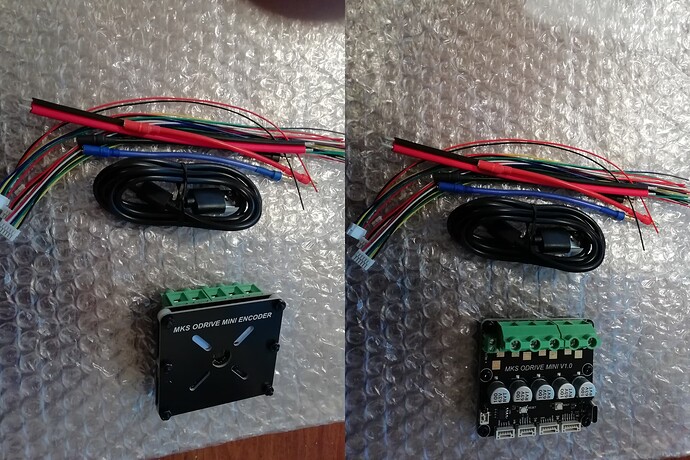
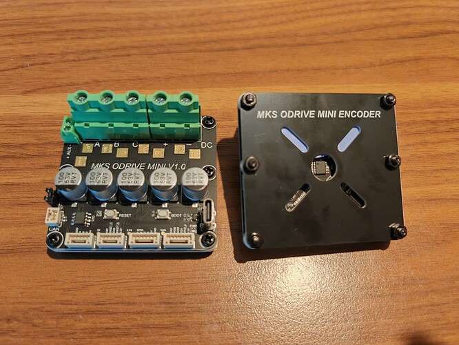
I’ve just received the card you found on Aliexpress with its encoder (really cheap).
I’ll try to test it over the weekend.
Hehe ![]()
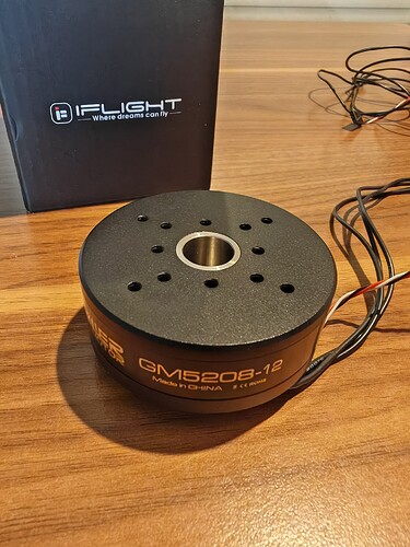
Of course we’ll share the code, I’m thinking of testing it with an iPower GM5208-24 motor I have on hand.
https://fr.aliexpress.com/item/4001296722586.html
Hihi lol Copieur !
Hihi lol Copycat!
I’ve just tested the latest dev version of SimpleFOC,
everything is fine on this version with the configuration used in this post.
Thank you for your work !
Code from my tests of Odesk 4.2 (version with scooter motor and hall effect sensor)
https://sourceforge.net/projects/openhardware-eu/files/STM32F405RGT6/
Short video
https://master.dl.sourceforge.net/project/openhardware-eu/STM32F405RGT6/STM32F405RGT6.MP4
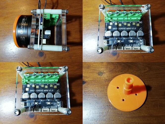
First attempt to implement a GM5208-24 motor with the ODESC 4.2 board and an AS5047P
Tests to follow …
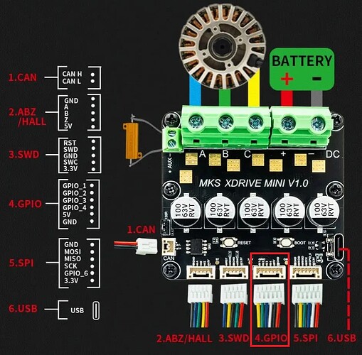
The map schematics are here:
https://github.com/makerbase-motor/ODrive-MKS/blob/main/Hardware/MKS%20ODRIVE%20MINI%20V1.0%20Schematic.pdf
I still can’t understand why it was so cheap, based on the schematics it has the same STM32F405RGT6 chip, same DRV8301DCAR driver, and the same NTMFS5C628NLT1G mosfets as the XDRIVE-S but has a AS5047 encoder for about 20e less
https://www.aliexpress.com/item/1005006314725836.html
But it’s not available anymore, maybe it was a mistake
The braking resistance was missing although it’s listed
Yes, I don’t understand the price, we’ll see if it comes back, and at what price …
for the moment I’m trying to read the AS5047P, but I can’t seem to do it.
/*
  SimpleFOC MKS DRIVE MINI + AS5047P
  SimpleFOC_STM32F405RGT6

  Odrive 3.6 ==> Odesk 4.2
  https://github.com/makerbase-motor/ODrive-MKS/tree/main/Hardware

  AS5047P
  https://github.com/simplefoc/Arduino-FOC-drivers/tree/master/src/encoders/as5047

  Makerbase-Mini contrôleur de servomoteur sans balais XDrive, haute précision, basé sur ODriLi3.6 avec AS5047P à bord
  https://fr.aliexpress.com/item/1005006480243178.html
*/

#include "Arduino.h"
#include "SPI.h"
#include "SimpleFOC.h"

//▬▬▬▬▬▬▬▬▬▬▬▬▬▬▬▬▬▬▬▬▬▬▬▬▬▬▬▬▬▬▬▬▬▬▬▬▬▬▬▬▬▬▬▬▬▬▬▬▬▬AS5047_SPI▬▬▬▬▬▬▬▬▬▬▬▬▬▬▬▬▬▬▬▬▬▬▬▬▬▬▬▬▬▬▬▬▬▬▬▬▬▬▬▬▬▬▬▬▬▬▬▬▬▬
// magnetic sensor instance - SPI
#define CS PA15 // GPIO 7 ==> PA15 ==> SPI(AS5047)
#define SPI_MISO PC11
#define SPI_MOSI PC12
#define SPI0SCK PC10 // PC10

// MagneticSensorSPI(int cs, float _cpr, int _angle_register)
// config           - SPI config
//  cs              - SPI chip select pin
// MagneticSensorSPI(MagneticSensorSPIConfig_s config, int cs)
//MagneticSensorSPI sensor = MagneticSensorSPI(AS5147_SPI, CS);
//MagneticSensorSPI sensor = MagneticSensorSPI(AS5047_SPI, CS);

MagneticSensorSPI sensor = MagneticSensorSPI(CS, 14, 0x3FFF); // // alternative constructor (chipselsect, bit_resolution, angle_read_register, )

// https://github.com/simplefoc/Arduino-FOC/blob/ee2dfdeee62bc28fdee5820fb1d26a0af4dc80c9/src/sensors/MagneticSensorSPI.cpp
// https://github.com/simplefoc/Arduino-FOC/blob/master/examples/utils/sensor_test/magnetic_sensors/magnetic_sensor_spi/magnetic_sensor_spi_alternative_examples/stm32_spi_alt_example/stm32_spi_alt_example.ino
// these are valid pins (mosi, miso, sclk) for 2nd SPI bus on storm32 board (stm32f107rc)
// SPIClass SPI_2(mosi, miso, sclk);
SPIClass SPI_2(SPI_MOSI, SPI_MISO, SPI0SCK);

float Angle;
float Angle2;
float Velocity;

void setup() {
  // initialise magnetic sensor hardware
  sensor.clock_speed = 500000;
  sensor.init(&SPI_2);
  _delay(2000);
} // End setup

void loop() {
  sensor.update();
  Angle = sensor.getAngle();
  Angle2 = sensor.getSensorAngle();
  Velocity = sensor.getVelocity();
  Serial.print(Angle);
  Serial.print("\t");
  Serial.println(Velocity);
} // End loop
Someone on discord who was in contact with the vendor remarked that they were just out of stock for now and that the shop will add more on Feb 20. (supposedly)
@VIPQualityPost prefect ![]()
AS5047P is now working properly.
/*
  SimpleFOC MKS DRIVE MINI + AS5047P
  SimpleFOC_STM32F405RGT6

  Odrive 3.6 ==> Odesk 4.2
  https://github.com/makerbase-motor/ODrive-MKS/tree/main/Hardware

  AS5047P
  https://github.com/simplefoc/Arduino-FOC-drivers/tree/master/src/encoders/as5047

  Makerbase-Mini contrôleur de servomoteur sans balais XDrive, haute précision, basé sur ODriLi3.6 avec AS5047P à bord
  https://fr.aliexpress.com/item/1005006480243178.html
*/

#include "Arduino.h"
#include "SPI.h"
#include "SimpleFOC.h"

//▬▬▬▬▬▬▬▬▬▬▬▬▬▬▬▬▬▬▬▬▬▬▬▬▬▬▬▬▬▬▬▬▬▬▬▬▬▬▬▬▬▬▬▬▬▬▬▬▬▬AS5047_SPI▬▬▬▬▬▬▬▬▬▬▬▬▬▬▬▬▬▬▬▬▬▬▬▬▬▬▬▬▬▬▬▬▬▬▬▬▬▬▬▬▬▬▬▬▬▬▬▬▬▬
// magnetic sensor instance - SPI
#define CS PA15 // PA15 // GPIO 7 ==> PA15 ==> SPI(AS5047)
#define SPI_MISO PC11 //
#define SPI_MOSI PC12 //
#define SPI0SCK PC10 // PC10
/*
MagneticSensorSPIConfig_s AS5047P_SPI = {
  .spi_mode = SPI_MODE1,
  .clock_speed = 1000000,
 .bit_resolution = 14,
 .angle_register = 0x3FFF,
 .data_start_bit = 13,
 .command_rw_bit = 14,
 .command_parity_bit = 15
};
MagneticSensorSPI sensor(AS5047P_SPI, CS);
*/

// MagneticSensorSPI(int cs, float _cpr, int _angle_register)
// config           - SPI config
//  cs              - SPI chip select pin
// MagneticSensorSPI(MagneticSensorSPIConfig_s config, int cs)
MagneticSensorSPI sensor = MagneticSensorSPI(AS5147_SPI, CS);
//MagneticSensorSPI sensor = MagneticSensorSPI(AS5047_SPI, CS);
//MagneticSensorSPI sensor = MagneticSensorSPI(CS, 14, 0x3FFF); // // alternative constructor (chipselsect, bit_resolution, angle_read_register, )

// https://github.com/simplefoc/Arduino-FOC/blob/ee2dfdeee62bc28fdee5820fb1d26a0af4dc80c9/src/sensors/MagneticSensorSPI.cpp
// https://github.com/simplefoc/Arduino-FOC/blob/master/examples/utils/sensor_test/magnetic_sensors/magnetic_sensor_spi/magnetic_sensor_spi_alternative_examples/stm32_spi_alt_example/stm32_spi_alt_example.ino
// these are valid pins (mosi, miso, sclk) for 2nd SPI bus on storm32 board (stm32f107rc)
// SPIClass SPI_2(mosi, miso, sclk);
SPIClass SPI_2(SPI_MOSI, SPI_MISO, SPI0SCK);

float Angle;
float Velocity;

void setup() {
  // initialise magnetic sensor hardware
  //sensor.clock_speed = 500000;
  sensor.init(&SPI_2);
  _delay(2000);
} // End setup

void loop() {
  sensor.update();
  // Read variables on STMViewer and St-Link V2
  Angle = sensor.getAngle()*1.0;
  Velocity = sensor.getVelocity();
} // End loop
The card works great! ![]()
I’ve just tested it in foc_current & velocity mode with success.
All that’s left is to fine-tune the P.i.D.
And a good STM32 coder will have to add ADC management for read temperature and also to read a potentiometer with analogRead()
I’m sharing my current code with you.
https://sourceforge.net/projects/openhardware-eu/files/SimpleFOC_MKS_DRIVE_MINI/
I played around with the board yesterday, for some reason in closed loop/voltage mode with hall sensors it didn’t work well.
I need to figure out why this weekend.
