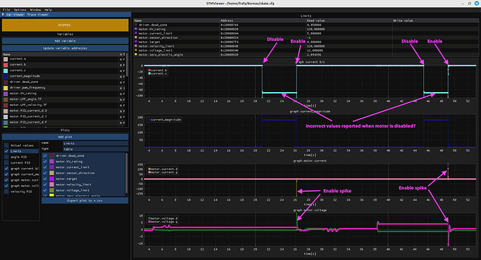
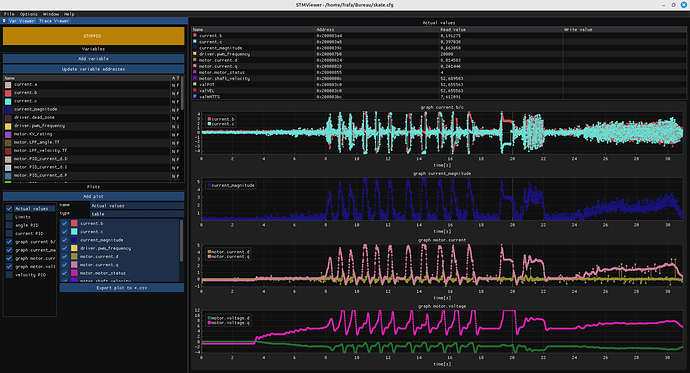
So this is the situation, am I correct?
@runger : Yes, exactly
@runger,
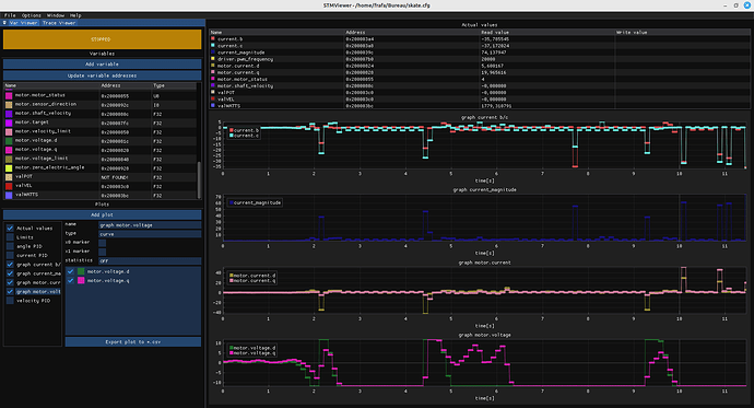
I would like to point out that measuring this current works very well if I do not disturb the loop.
it’s exactly the same problem as with analogRead()
I just did a test by simply adding at the start of the loop ==> delay(100);
Look what that gives…
EDIT:
As soon as I insert a slowdown, even a very short one, the current measurement no longer works correctly…
EDIT2:
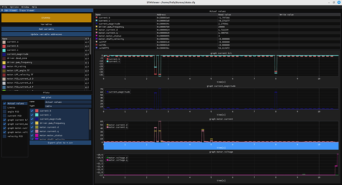
motor.voltage_limit = 0.5f * driver.voltage_limit;
motor.current_limit = 5.0f;
I don’t think it’s the same case.
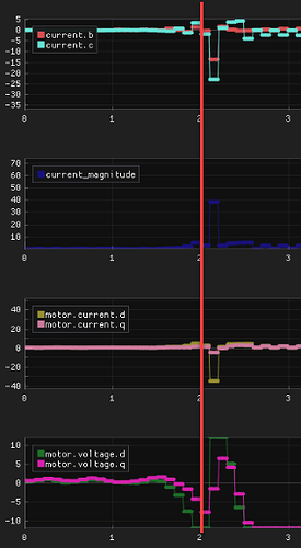
This looks like the PI is overshooting because the control loop is slow.
The peaks are much lower, the current could be correct here.
Is this the master branch or dev branch?
I still don’t think it is right. The peaks are smaller for some reason, but still unexpected:
We see in the “flatter” regions a square-wave pattern, this is expected. There are about 10 square wave oscillations per second, as expected with delay(100). This is the controller overshoot first one way and then the other way as it reacts to the long delta-T.
But the peaks, where the samples suddenly drop down to -35A, I don’t think it is expected.
I wonder what’s causing it. It seems the common factor between the delay(100) and enable()/disable() test cases is a long delta-timestamp?
Ok I got your point, still I have the feeling it’s not the same issue.
Is this happening at high pwm duty cycle ?
With low side current sensing and only 2 phase currents, high pwm duty cycle might not allow enough time to sample the phase currents.
I use the dev branch
The problem is exactly the same on B-G431B-ESC1 boards.
it’s the overtaking that bothers me …
Hmmm… since you are using low side sensing, you can only sense when the low side FETs are on. Maybe these readings correspond to a “miss” on the ADC and the PWM low side active period.
You have driver.voltage_limit == driver.voltage_power_supply.
Could I ask you to test it with:
driver.voltage_power_supply = 24.0f;
driver.voltage_limit = 20.0f;
And see if the problem still happens?
B-G431B-ESC1 also uses low side current sensing, but because it has 3 phase currents, we could implement in the future a software trick to sample only the 2 phase currents with the lowest pwm duty cycle.
This is called Longest Zero Time in VESC:
With only 2 phase currents, there is no trick, you have to limit the duty cycle.
You can go slightly higher by shifting/delaying the current sampling time.
You are absolutely right, and we should implement this ![]()
But I’m still confused, and not sure it’s related to the problem yet. Because we get these spikes in a situation where the current is around 0 anyways. So the differential measurement (low side) is giving close to 0, and then suddenly there is a spike to a very large negative current. That would be like the current sense amp suddenly dropping from its centre-point (0A) to 0V (-Amps). Why would it do that?
In those terms it seems more likely the ADC side of the MCU is having some problem - normally it returns a value around the centre-point voltage, but occasionally it returns a 0V reading. But why?
And is it the case that it is doing this all the time, and having a low delta-T just means it gets quickly compensated and we don’t see it, or is the high delta-T somehow causal, as the enable()/disable() test seems to suggest?
-Edit- or could it even be a power issue, solved perhaps with more bypass capacitance for the current sense amplifiers?
At least the first occurence happens when voltage is high:
Current is probably low because there is no load and the hickups mess up with the scaling.
@runger
You’re right!
driver.voltage_power_supply = 24.0f ;
driver.voltage_limit = 20.0f ;
driver.voltage_power_supply = 24.0f ;
driver.voltage_limit = 24.0f ;
Also why is it looking like phase c current is half phase b current ?
@Candas1
I can’t explain the difference between phase b&c
I don’t have a B-G431B-ESC1 to compare,
B-G431B-ESC1 is at the university fablab, and we’re on vacation this week.
Which university? In France right?
Yes Ob.i LAB in France in Montpellier
https://iut-montpellier-sete.edu.umontpellier.fr/liut/obilab/
Hey,
So we’ve found a cause - when the duty cycle can go to 100% - but not really the explanation.
Which current sense amps are used? I would have expected the differential voltage across the shunt to read 0 when the low side FETs are closed, but apparently not? Apparently its reading as a large negative current flow, so a negative differential voltage?
Could it be a sampling arfifact? That picture still looks to be with the 100ms delay, so perhaps the delay and the commutation speed are multiples of each other such that you’re always sampling a similar point in the electrical revolution?
I have no idea what current sensors are used,
the seller doesn’t provide any shemas and if you search on the internet you’ll find almost nothing about “ODESC 4.2”.
the only thing the seller can say is that the card is 100% compatible with “Odrive 3.6” …
Captured below without delay and at 50 rad/s
I hold the motor by hand from time to time to increase the current…
In these conditions, the SiimpleFOC-controlled engine works very well.
Ok, so it will be hard to find out what’s going on, unless you feel like setting up a major debugging with the oscilloscope, etc…
But you have a workaround for the moment (don’t use the max PSU voltage), and we have a TODO for the code: include the idea of minimum on-time and eliminate phases with too low on-time from the sensing.
So if you’re happy we can leave it there for now…
Thank you both, we’ll leave it at that for now ![]()
I think I’ll come back to you next week for “B-G431B-ESC1”.
as I’m pretty sure she’s having the same problems.
