Gate driver chip has the GND pin connected to DGND
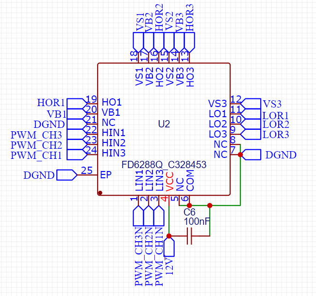
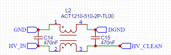
DGND is connected to GND through common mode choke (inductor)
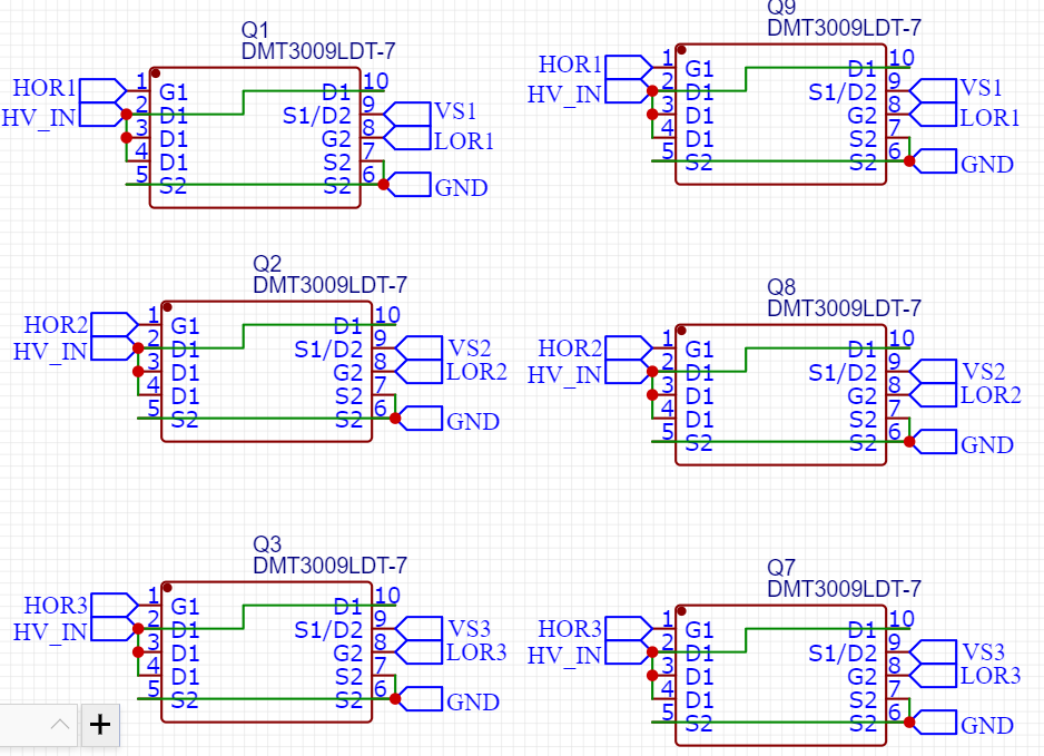
The low side MOSFETs have source pin connected to GND
I have checked all 4 layers, and DGND is not shorted to GND.
Gate driver chip has the GND pin connected to DGND
Correct. Probably I misunderstood since you say
I assumed you mean the low side mosfet power ground return path, while you were referring to the gate driver.
No worry, you are correct. Yes, that’s by design. People can change it. Better draw a GND to the driver instead of removing the split ground but whatever anyone fancy. I usually split three grounds at work (driver has separate) and here I only split once so probably not very optimal, but hey… good conversation, thank you. Very educational.
Cheers,
Valentine
It’s tempting to use your rev 4 design but I have to be serious and not stray/mission creep. My goal is to finally finally get a board that is generally useful more broadly than that. We need to stop this endless cycle of repeating effort for boards in this price bracket and as a community get at least one fully known good actually working board actually done…
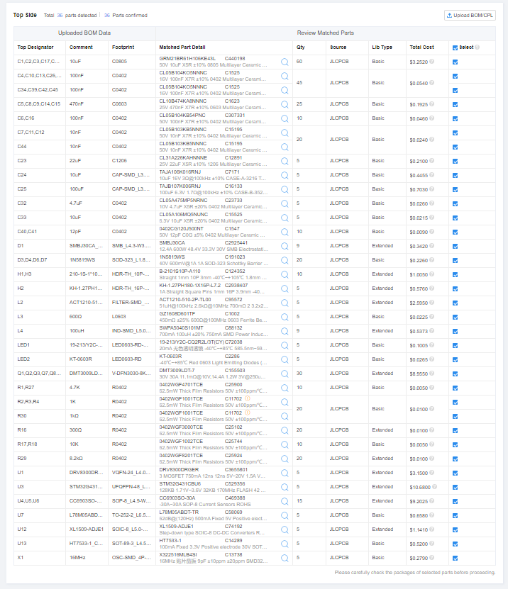
I’m trying to clone the design to make this mod, but I am not confident the software is as slick as it seems to think it is. Exactly where is the bom stored? I see a schematic and a file of vector layers that can become a gerber file. I see no bom anywhere… is it inside the schematic file or derived from it later or what?
In Easyeda, the BOM is generated based on components in schematic file. So derived later.
The main problem is that everyone has different requirements, which usually cannot all be fulfilled simultaneously. Some people want extremely cheap <$10 drivers while other people want high performance designs. Some people want UART or USB, while other people want I2C or CAN etc. And some people want small boards while other people don’t care about the size. And everyone has different sensor types on their motor making it difficult to have a universal sensor connector.
If you try to add more communication interfaces, it makes the board bigger. If you try to make the board smaller, it becomes more expensive and you might sacrifice on connectors. If you try to increase performance usually the size and cost also increases.
My version 4 board was originally designed as a one size fits all, using cheap components, but then I wanted higher current, higher efficiency, smaller size, and less duty cycle distortion caused by dead time, so I made version 5 (which costs around 3x as much as v4). But now I have found even more ways to increase efficiency and I want to support 48V motors, so I am contemplating making a version 6.
If we want a one size fits all solution, we should probably run a poll or something to gather peoples requirements, before trying to design a board to meet most of them. Otherwise we will make a board that only caters to 20% of people, and there will be a lot of repeated effort.
![]()
Cheers,
Valentine
But there is a vacuum for sure in this particular $11 usd category, with specs like the odrive micro which is >$100 usd.
I would also have issues you describe with dead time probably, and if we wanted to implement high frequency injection we’d probably want finer control over the mosfets than the drv chip gives. I don’t know, I’m just saying something seriously deeply programmable is important.
My solution for variety is to start with at least one that is a good bet. Then, yes, people can make variants. But it helps hugely to have at least one fully good working board that other people also use because they make code for it and get the various features working and so on which is really important for the Arduino paradigm, where modularity and relatively low training and labor input for doing a given thing is prized.
I’m not saying one size fits all, I’m saying let’s pick a good solid bet and get that all the way done, then variants can happen relatively easily. Right now we are really sliding, board after board that’s got issues pretty deep down. It has to at least work.
The people who developed the raspberry pi or pico or arduino flagship boards could have said the same thing. But they saw progress is possible. You make one well designed relatively broadly applicable board and people start using it, which proves the design and gets the bugs out, builds the code base, then people can produce variants with relatively little effort if needed. Eventually you learn enough and technology and ecology develops around you enough that it’s time for the next version.
The B-G431-ESC1 board is definitely useful, partly because it was relatively cheap, available and so people started using it, getting features working etc. But clearly it is not good enough in many ways. Progress is possible. We can do better than that, we can do better than the simplefoc boards currently on the website. That’s all I’m suggesting. Not a one size fits all. A good solid bet like the arduino or the Pico, which is actually worth pushing through to a good state of development, which takes forever, and which can then be a cornerstone of something more.
ok, I modified the ground of the driver to be the main ground, before the filter, not after. Here is a link to the project, not sure it will work. 账户-嘉立创EDA
I was checking it before ordering and something has gone wrong. There is tons of copper just missing from the high voltage and ground. Checked the layers, they are all visible. The design does not reflect the picture shown in the preview on the web page.
Valentine, perhaps you are working on the design and it’s in an intermediate state and I should buzz off until the dust has settled? I can’t get back to the working design now to clone and modify the ground. I would have to re-route/pour new areas which I don’t really know how to do efficiently though maybe I could muddle through…
Hi Anthony,
I’m not working on the design. I’m at work the earliest I can check on this is tomorrow.
Cheers,
Valentine
I double checked all the copper pours are present.
Please double check.
Cheers,
Valentine
Modded the driver to use GND.
If I get time I’ll refresh the components with in stock, but not sure it’s worth the effort as stocks change daily.
Cheers,
Valentine
Ok, my wacky issue with the ground pour and high voltage region has evaporated, probably I messed something up. I will keep checking every day or so and order as soon as the driver chips are back in stock :). I think this is going to be good progress. I got the grant so I feel obliged to do something at least slightly useful to others, which I think this will be, although I could probably use that board 2 rev 4 I’m going to resist the temptation to take that route :). Definitely feels more revolutionary ;).
Let me check on the drivers.
The driver I used is a chinese knockoff of TI’s DRV8300, if you are really getting a grant $$$ (someone else is paying?) it’s worth me spending some time on this and creating a genuine DRV8300 variant of the board.
Cheers,
Valentine
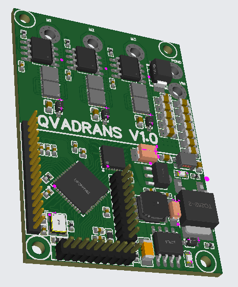
Updated with the latest in stock. Changed the driver to drv8300.
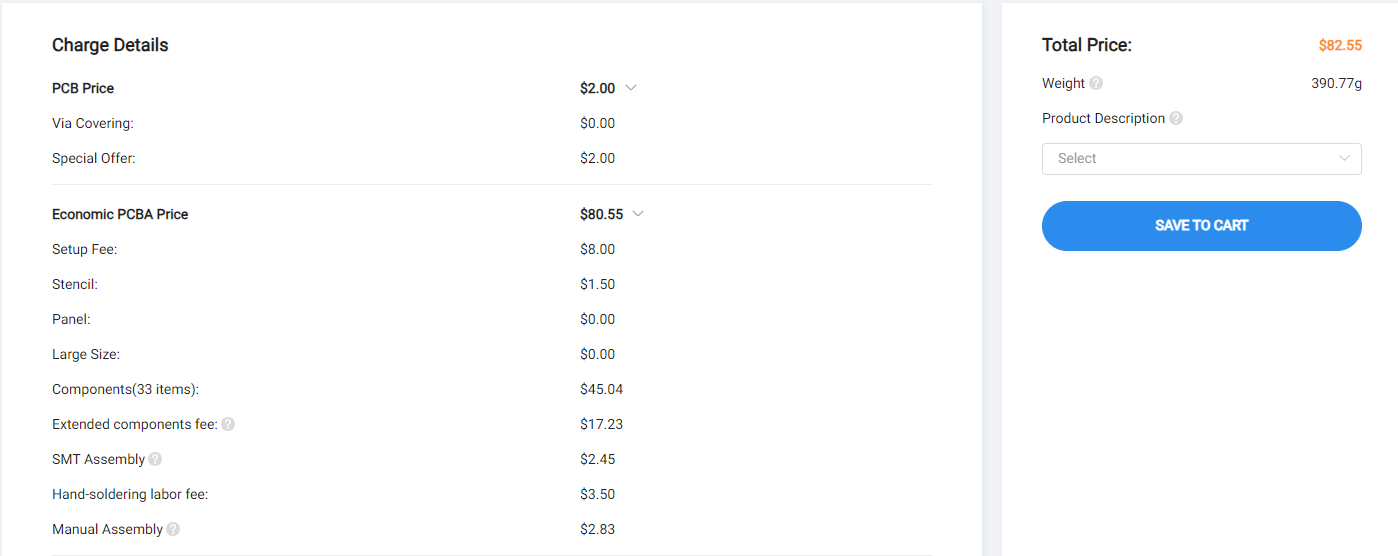
For a batch of 5 came at about $16 per board.
DRV8300D doesn’t need bootstraps but I left them in case we change it back to Fortior. You can remove them from the BOM if you want to make it a little cheaper.
Cheers,
Valentine
Awesome, I will investigate and try to order soon. The grant is not large, but it’s enough to pay for parts and stuff. Enough to let me take this seriously and not be tempted to give up at every turn :).
Update: ok I think I put it through correctly, checked everything when prompted and stuff, looks good!
Definitely going back to the cheaper drivers would be a good idea for longer term, but at least it’s only four layers.
It gave a warning that M1,M2 etc are not in the bom but they are vias :P, not supposed to be in the bom I assume.
For my energy recovery ventilator longer term I’ll probably try to shave some bucks off but it’s not clear. Even if I could shave $5 per board off, it would take a long time to pay back just the work it takes to do that, esp with even a minor hiccup. That’s partly why I am so keen on a board that is a reasonable intermediate for a broad range of uses, like the pico W. If it’s a couple bucks more, few people are going to care. That it’s tested and has the specs needed, that matters a lot though. So this is the right path, good components etc even if they are a little pricey. But I’m glad it’s not 6 layers like that other board, that was expensive.
uh oh, wait a second, the footprint and pinout of the two drivers is exactly the same?
nope. Looked at the datasheet, the pins are different. I guess the board wasn’t done, I need to update the pcb stuff and redo the routing for the driver chip. I’ll come back to it tomorrow. I cancelled the order for now.
Pins are absolutely identical except the mode which is left floating.
Not sure what you are looking at.
Cheers,
Valentine
Page 4 , 24 pin vqfn, top view. Is that not correct? Those three pins in the lower right hand corner should be ground for instance, no?
It’s rotated so pin 1 is bottom left.
oh yeah, nice. I see the little dot for orientation has also been relocated, so everthing should work. I will try again to order. Thanks…
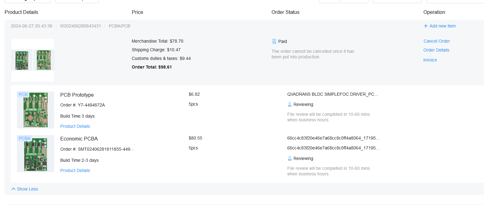
ok take two has been submitted, they indicate production starts july 3 and 8-12 days shipping so uh maybe july 18 should be able to give it a spin :D. I recall and have my notes from the lepton 2.0 and have some experience with the B-g431 board so I think I will be able to do most of it ok. I’ll probably take the arduino files for the b-g431 board and modify them so we inherit the various stuff that already works from that :). I know the current sensing will require getting in there to get that working and stuff, I’m sure.
I’m sure it will take a fair bit of doing to get all the features that work on the b-g431-esc1 board working again on this board, but we certainly have a good head start. It was $20 USD per board for 5 boards including shipping which really can’t be beat and it’s got the solid processor and current sensing and lots of current capacity and stuff. All the pins are broken out so very flexible, stuff like that. Always lots to do but this is progress…