You’re probably better off using the generic stm32g4 implementation unless the current sense is routed to pins that only have opamps and not ADC inputs.
1 Like
![]()
Should I pay it, or try to modify the design, or try to persuade them to do it without paying more? Maybe it’s just a money grab? I have no idea, I don’t order boards very often…
I may have made a mistake submitting the order, it’s really not clear.
My main concern is not trying to prematurely validate a design that still warrants changes. That would be inefficient.
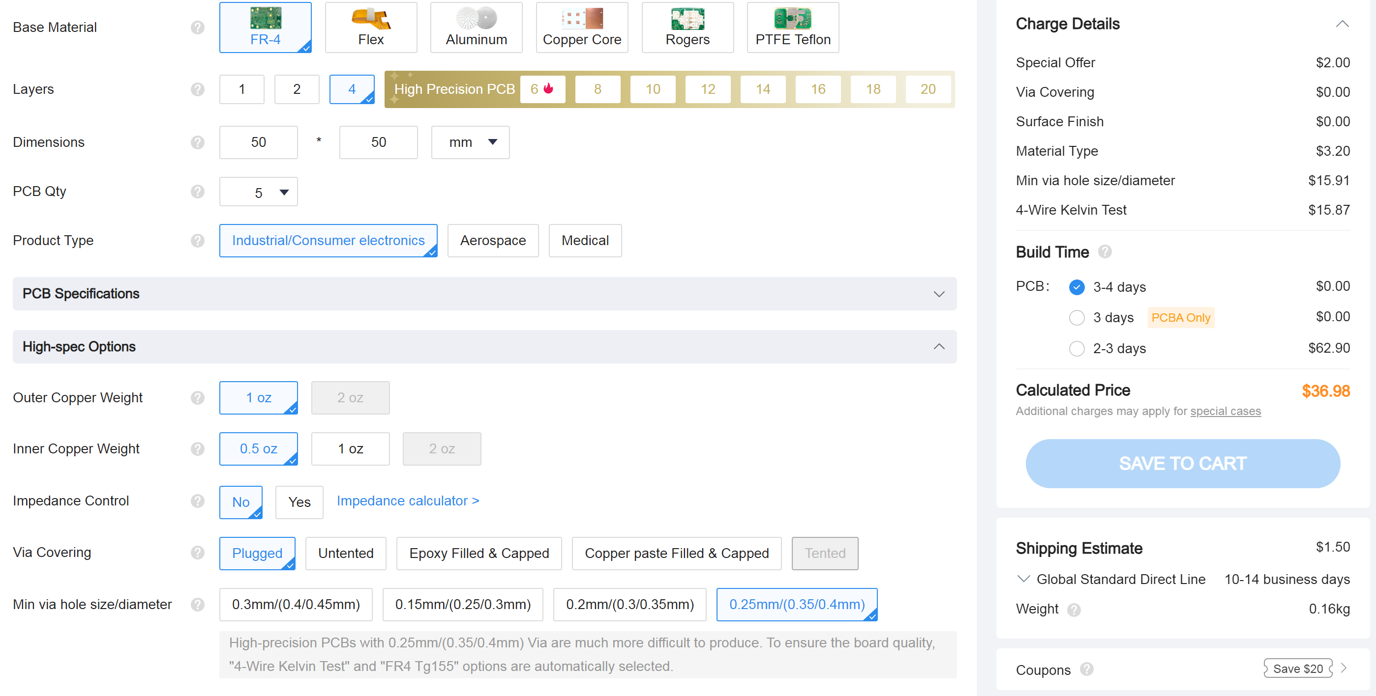
Should I try to get in there and make the vias bigger and resubmit? They are about 0.2 mm diameter, I had a look. To be fair that’s pretty small I guess.
Thanks for placing your order on JLCPCB.COM.
You need to pay additional 34.85 for your order. QVADRANS BLDC SIMPLEFOC DRIVER_PCB__20240628133142.zip_Y8【4494872A_Y8】
Reason:
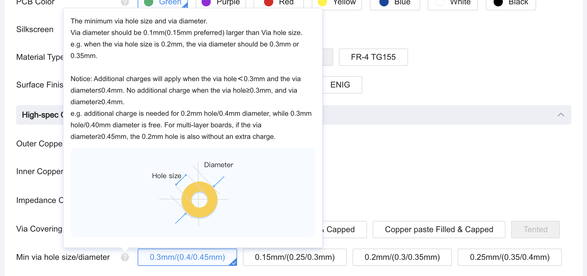
1.There are minimun hole size of 0.2 mm, with a diameter of 0.4 mm in your file, to ensure the quality for your order, the 4-Wire Kelvin Test is recommended,so you may need to pay for an extra cost for it.
Please note that this batch order won’t be put into production if funds have not been received.
How to pay:
You can email them and tell them to ignore the 4-wire test and just make it. Tell them you accept the risks. Some time whoever does the dfm is very anal and try to get extra money from the customers.
There are no vias 0.2 mm, they are lying. The smallest via is 0.25mm.
Valentine
1 Like
I have checked the PCB files on OSHWLab, there are a few errors in the file so that’s probably why JLCPCB is complaining. To find the 0.2mm hole vias, open up the design rules:
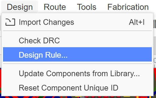
Change via drill diameter to 0.25mm
Note: 0.25mm hole vias cost extra from JLCPCB, the free vias have diameter 0.45mm and drill 0.3mm

Then go back to the previous design menu and click Check DRC. It will highlight with a cross which vias are too small.
There is also a via overlapping with a PTH (on PA11), so the via will need to be removed, otherwise there is a risk it will not be manufactured correctly.

Also the copper to board outline is 0.15mm. This is smaller than JLCPCB’s capability of 0.3mm, which means you might end up with exposed layers on the sides of the PCB, which could cause shorts if the edge of the PCB touches some metal. It is up to you whether this is acceptable or not.
If you are using VCUT panelisation (due to PCB assembly), the copper to board outline needs to be greater than 0.4mm on the sides which have VCUT.
Also I’d suggest adding more vias under the STM32 (suggest around 10), and filling in the inner layers under the STM32 completely with GND, this will improve the thermal and noise performance of the board.
Also you should replace the TVS diode with a unidirectional one, to better protect against reverse voltage.
1 Like
Ok, I will slate this for doing later, unfortunately I can’t do it now. I’m open to paying someone to do such things, I am supposed to make 10 fully functional fans by july 23 and I don’t think I’m going to make it…I may be able to do that with b-g431-esc1 boards but the current measurement is too noisy for the sensorless approach I’ve been using.
0.25 drill / 0.40 aperture are free on JLC with 4-layer boards!
1 Like
I fixed all minor issues everyone noticed, except the TVS diode, that one stays bidirectional. I disagree with the reverse voltage suggestion.
Most importantly, the vias are now 250/450 microns, that should be sufficient not to trigger the JLC warning.
Let me know how it goes.
Cheers,
Valentine
1 Like
One more thing, if you’re going to stick to split ground, try to route DGND close to CSx and 3.3V, this way all 3 traces will be very close to each other and it will improve noise immunity slightly.
Thanks, I will look into this when I get time.
Cheers,
Valentine
Also I found this MOSFET which you can consider switching to, to save cost, DMN3009LFVW-7 $0.2255 each, the original dual mosfet cost $0.42 each, and you used 2 of them. Switching to this one will also make your gate traces routing less messy and should reduce ringing.
1 Like
That’s future improvement, thank you. I don’t have time for that now unfortunately.
This is not a production grade design.
Cheers,
Valentine
ok this is awesome, I feel bad for not doing it, I have been having difficulty being extremely tired and also have deadlines looming :(. However I am in this for the long haul, I think it is a sound design that is the outcome of a long constructive process and has a lot of wisdom built into it now which is really going to pan out.
I’ll go through the process of placing the order, carefully of course and with less dumbness and impatience than last time, very soon.
1 Like
Ok order placed!
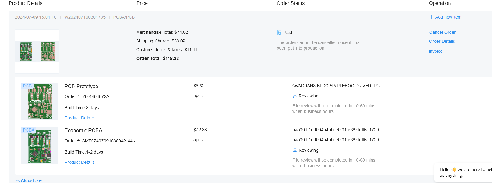
I got the DHL shipping option, I’ll have to pay the brokerage fees and customs but it should get here by july 17, they said, whereas the other shipping option was an extra 10 days or so.
I’ll prep for arrival by refreshing my memory on how to program STM32 and get it working with Arduino etc. ![]() Stoked! I’m grateful to be part of laying a tiny bit of foundation that hopefully many others will appreciate and stand upon, as I have many times with many other things :).
Stoked! I’m grateful to be part of laying a tiny bit of foundation that hopefully many others will appreciate and stand upon, as I have many times with many other things :).
1 Like
The boards should arrive any day now, if anyone wants one and can share their code or whatever to contribute, let me know and I can mail you one. I only ordered 5 and I should keep 2. One is going to Runger so he can make proper board files (I’ll bodge something so I can get on with my stuff but would have a hard time making proper files), but the mail takes a while. After debugging/being sure the board works well enough, I will order more and can send a few more out to anyone who would like to help get the ball rolling by recording their experience etc., so we can get the community documentation up to a level comparable to the B-G431_ESC1 board sooner rather than later i.e. you can search and find info on what you need to do to get the various features working, example known good code for basic drivers etc.
I’ll be doing a basic hall sensor torque driver with switch type halls and Deku’s SmoothingSensor as my contrib to the code base, also getting basic current sense working ok (for current limiting for redundant safety, and may be useful for other stuff). I plan to produce a set of test programs and procedures too.
Success! (the forum will not allow me to make a separate post, so I can only edit this one rolleyes)
The boards arrived in the morning, and I spent until now getting things working, mostly. 8 hours…
just so the next person, who may be quite new at this knows:
you need the latest version of arduino, I started with 1.8.something and it kept saying there was an error finding a file that it needed for uploading the program.
you need of course an st-link.
You need to install stm32cubeprogrammer, which arduino then summons automatically to upload the program over the stlink
I soldered wires directly to the through-holes that were meant for the 1mm pitch connectors.
PA13 is SWIO, PA14 is SWCLK, PA6 is USART1 TX, PA7 is USART1 RX, PC11 is the amber led on the board, and the pins for the inverter are in the sketch there.
Don’t forget the ground pins of course.
I used an uart-usb converter with manual voltage jumper pins set to 3.3 volts of course.
I did a crude measurement of the clock speed and it seems to be about right (8 blinks every 10 seconds with 1250 millisec per blink), there is some value that can be printed which verifies this.
You need to install stm32duino arduino code libraries (using arduino’s library manager) and also the board files (by adding the url to arduino so the boards will appear in board manager).
I was not able to get the board file json in the repository working (QVADRANS-SimpleFOC-Controller/boards at main · Spacedays/QVADRANS-SimpleFOC-Controller · GitHub). That could help as it would set clock speed
I instead used the generic g431… board and then selected the g431CB… board.
I am so tired of the messiness that is arduino… So glad I don’t have to use this for most things most of the time. Even the board files are such a mess, so many different files to mod and tweak and get working manually, I gave up but this isn’t a bad approach for now, except the clock speed or somesuch may be wrong.
Here is the program for blink:
#include <Arduino.h>
void setup() {
  pinMode(PC11, OUTPUT);  // LED_BUILTIN
}


void loop() {
digitalWrite(PC11, HIGH);
delay(500);
digitalWrite(PC11, LOW);
delay(500);
}
Here is the program to print to serial, which also blinks just so you know it’s running:
#include <Arduino.h>


void setup() {
  Serial.setRx(PB7); // using USART pin name PY_n
  Serial.setTx(PB6); // using USART pin name PY_n
  Serial.begin(1000000);
  pinMode(PC11, OUTPUT);  // LED_BUILTIN
}

void loop() {
  Serial.print("HB");
  delay(250);
  digitalWrite(PC11, HIGH);
delay(500);
digitalWrite(PC11, LOW);
delay(500);
}
Here is the open loop test:
#include <SimpleFOC.h>
BLDCMotor motor = BLDCMotor(7); //different for each motor
BLDCDriver6PWM driver = BLDCDriver6PWM(PA8, PB13, PA9, PB14, PA10, PB15);//this line must be changed for each board!
void setup() {
  driver.voltage_power_supply = 24;
  driver.init();
  // link the motor and the driver
  motor.linkDriver(&driver);
  FOCModulationType::SinePWM;
  motor.voltage_limit = 2;   // [V]
  motor.velocity_limit = 300; // [rad/s]
  motor.controller = MotionControlType::velocity_openloop;
  motor.init();
  motor.voltage_limit = 2;
  motor.target = 2;
}

void loop() {
     motor.move();
}
the next step will be to get the hall sensors working. Then smoothingsensor. Then get it working in voltage mode torque mode. Then get it to measure current, hopefully this will go ok if I follow the simplefoc docs for using the analog read etc, I will calculate an equivalent resistance that gives the same volts/amp as the hall sensors. Then get it to communicate critical bits of data over serial (I have some snippets that should help a lot with this, from the b-g431-esc1 board driver thing I was using).
Then implement stall detection.
Then go back and try to make it quieter.
there is probably the once per click rotation issue that I’ll have to modify the library again to solve, that’s ok, I still have my modified library and notes somewhere and mostly remember, I think, and it might not arise again as that was in the open loop code stuff.
then test for reliability.
I’m making a notes file for modifications that I will eventually make, soldering it was really hard and I was afraid of bridging due to the small pitch.
2 Likes
I found that making a header file with the pin definitions makes it very easy to keep track of pinout changes between revisions and an easy reference to make sure that you have things set up correctly and consistently: lemon-pepper-stepper/firmware/include/lemon-pepper.h at main · VIPQualityPost/lemon-pepper-stepper · GitHub
2 Likes
That’s pretty awesome!
So the Qvadrans batch worked, with the latest mods, that’s excellent news.
Cheers,
Valentine
2 Likes
Hello. I’d also like one board to play with. As far as I know, Runger and I are in the same city in Austria). Is your offer still relevant?
I tried yesterday to send you a private message here on the site, but it apparently doesn’t get through, because I can’t even find it in the sent messages
1 Like
@Anthony_Douglas if you mail me 2 I’ll get one to @nikolaewich1988 ![]() we have been meaning to meet up anyways for some time…
we have been meaning to meet up anyways for some time…
2 Likes