I thought I did upload the pcb files to my github, but it looks like I forgot to or forgot to publish it. Ill try to upload those tonight when I get home. I maybe could have chosen better 1.27mm headers since ive had some issues programming it if i dont use test hooks, but that could also just be a janky wiring setup that im connecting it to. I dont know much about board design so make sure its what you want once I get it uploaded before ordering any
Hey @Zeno, you should be able to see all the files for my project here: GitHub - Spacedays/QVADRANS-Adapter-PCB: Adapter Board to break out comms pins for the QVADRANS 1.0/Lepton 3.0 board
Let me know if there’s any missing libraries or things like that, I haven’t shared a KiCAD project before so I might have missed something.
Great, thanks!
Will let you know if we made some adjustments or if something was missing.
I’m taking a deep dive here in getting to know the components, especially the STM32 chips ![]() .
.
We’ve ordered the boards and are now figuring out a way to get the LED blink test project to be loaded onto the STM32G431CBU6 MCU. I have some questions but maybe this is not the place to ask them, do let me know if it’s not the right spot!
-
Do I need to use a tool to specify the pinout on the STM32 to configure it for the QVADRANS schematic or is it dealt with by the PlatformIO - Arduino framework that we’re trying to use here?
I started looking into STM32CubeMX and this seems to give a lot of options to configure the pins but I’m unsure if I need to use the software tools from ST.com to get the chip ready. -
Do you guys use a regular USB to serial adapter and connect it to the TX RX contacts in a certain BOOT mode in order to upload the project via PlatformIO? If so could you help me locate which pins to use?
-
Or do you use a ST-Link device as I read in the previous LEPTON project thread and connect it to:
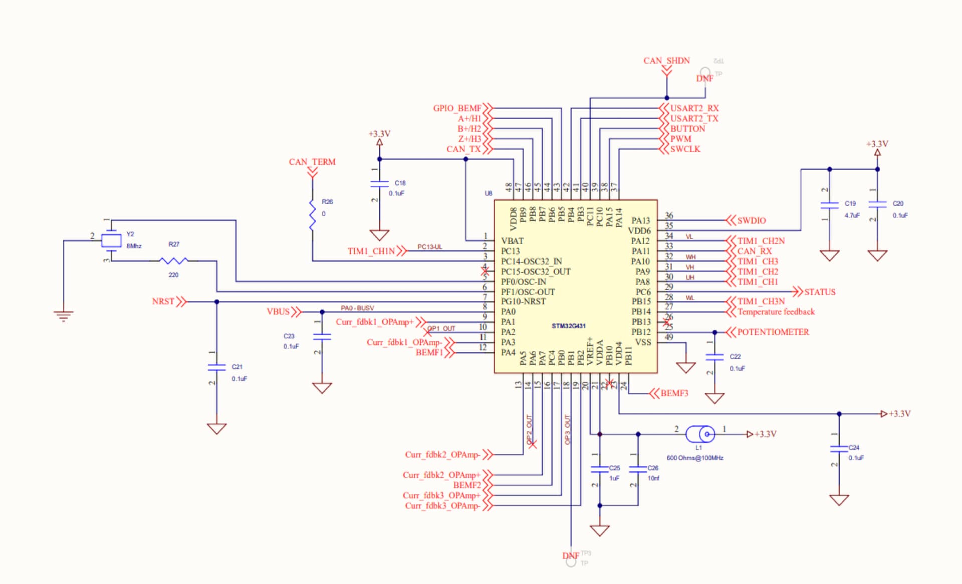
[STM32 pin - QVADRANS pin header - SWD protocol]
PA13 - PA13 - SWDIO
PA14 - PA14 - SWCLK
… - DGND - GND
PG10 - NRST - NRST
VDD - 3V3 - VDD IN
If you guys have some reference guides on where best to get started I’m more than happy to follow them! Been reading through a lot of stuff lately and it’s hard to collect the required documentation and tools to get started.
Unless you are taking the pin definitions from an existing qvadrans project (I don’t know if there are any?) then you need to take it from the schematic- if you are interested in exploring how to choose pinouts for chips in the future, a really great tool is STM32 CubeMX software - it is a frontend that lets you choose peripherals and shows you where compatible pins are.
If you pull up/down BOOT0 then you should be able to load a firmware from the booloader. You could do over UART0 Tx/Rx using a USB to serial adapter but I would recommend using an STLINK with SWD as it will let you debug too. That would go on PA13/14 for SWDIO/SWCLK. You don’t need to manually manage BOOT0 if using an STLINK
I didn’t have to do anything other than specifying the generic board in platformio that @VIPQualityPost helped me with before. The repo with my code has the board files I used, but I think I remember seeing something about the generic board getting merged into the main ST platform files… maybe that’s happened by now?
As for programming, I also use SWD with the STlink. The adapter board I put together has a set of headers with everything you need for programming (3v3 reference, ground, sck, swio) and a couple extras I’ve heard can be used in debugging.
Yes! The G431 is in the main ststm platform so you shouldn’t need to do any special hoops to get a project to build… just specify the board, platform, and framework to match like this: lemon-pepper-stepper/platformio.ini at main · VIPQualityPost/lemon-pepper-stepper · GitHub
But my files won’t help for your pinout for the actual motor control/sensors etc as it’s different from mine, so you should find the repo that @Pete_Bowsers has or just work it out from the schematic.
You guys are awesome but I’m still a bit confused:
- I don’t need to use a software tool like STCubeMX to configure the pinout on the STM32G431CBU6 like Valentine put a screenshot of in the EasyEDA file and upload it to the chip (see picture)?
- This means that the SWDIO and SWCLK pins on the chip ready “out-of-the-box”?
- Uploading code to the chip can be done by pulling the correct BOOT pin(s) up/down, this puts the chip into bootloader.
- To physically upload the firmware it’s easier to use the ST-Link module to use SWD (or JTAG). The pins necessary are available on the QVADRANS board as well on the break-out board by @Pete_Bowsers.
This is how I currently configured the platformio.ini file, it compiles:
I do want to use the generic board definition since I didn’t see any differences except for the f_cpu.
[platformio]
; change this if you want to compile for another board
; To distinguish in the code, use #ifdef <board macro> to enable board-specific code for each target,         e.g. #ifdef ARDUINO_AVR_PROMICRO16 et cetera.
env_default = genericSTM32G431CB

[env]
lib_archive = false
lib_deps_builtin =
    Arduino
        SPI
        Wire

lib_deps = askuric/Simple FOC@^2.3.2

[env:genericSTM32G431CB]
platform = ststm32@17.3.0
board = genericSTM32G431CB
framework = arduino
upload_protocol = stlink
; change microcontroller
board_build.mcu = stm32g431cbu6
; change MCU frequency
board_build.f_cpu = 170000000L
Correct, I just mentioned that for if you want to use the chip yourself in the future and want to explore the pinouts yourself. Indeed for a board you already have in hand you should just use the schematic.
Yes, you can disable them in firmware but generally they are always available unless you specify to disable them. You don’t need to go to the bootloader if you have the SWD pins enabled as the stlink can directly connect to the device itself through a special connection. If you want to use other upload methods, like UART, or DFU, then you use BOOT0.
Great!
If I understand this correctly I should create new board files to match the pinout on the schematic then?
I’ve found this guide/reference on how to achieve this since I want to work with Platform IO in the Arduino framework in order to use the SimpleFOC library: pio-custom-stm32duino-variants/README.md at main · maxgerhardt/pio-custom-stm32duino-variants · GitHub
I’m gonna try this out this week, thanks for all the support already!
No, don’t do a variant- it is quite complicated.
For the pinout, just create some file like qvadrans.h and put defines with your pins in there:
define U_H PA9 etc etc, then just include that in your project (or don’t and just put the pin names in your program, but that can be hard to read sometimes). If you want to make a variant, you could, but it’s far from necessary and quite complicated and I doubt the PIO people would want to upstream that anyway.
Hey there
Does anyone work with the STM Motor Control Workbench instead of simplefoc?
I do, and I tried to adapt the JSON configuration file of the ESC1 inverter board for the Qvadrans according to the online specifications here: https://wiki.st.com/stm32mcu/wiki/STM32MotorControl:Motor_Control_Boards_Description
I can upload the file if it helps.
This configuration file is read by CubeMX to assign the pins and to build the project. But it does not work, the problems are:
- The motor just vibrates at one position, but doesn’t turn around.
- The supply voltage collapses to about 12 V.
- The Qvadrans draws 3 A, which is the maximum of the power supply
- At rest (i.e. not turning the motor), the phase voltages are all at 9.12 V. Is this normal? I’ve measured the phases of the ESC1 too, they are at 3.25 V at rest.
I measured one phase with the oscilloscope, and it looks very strange:
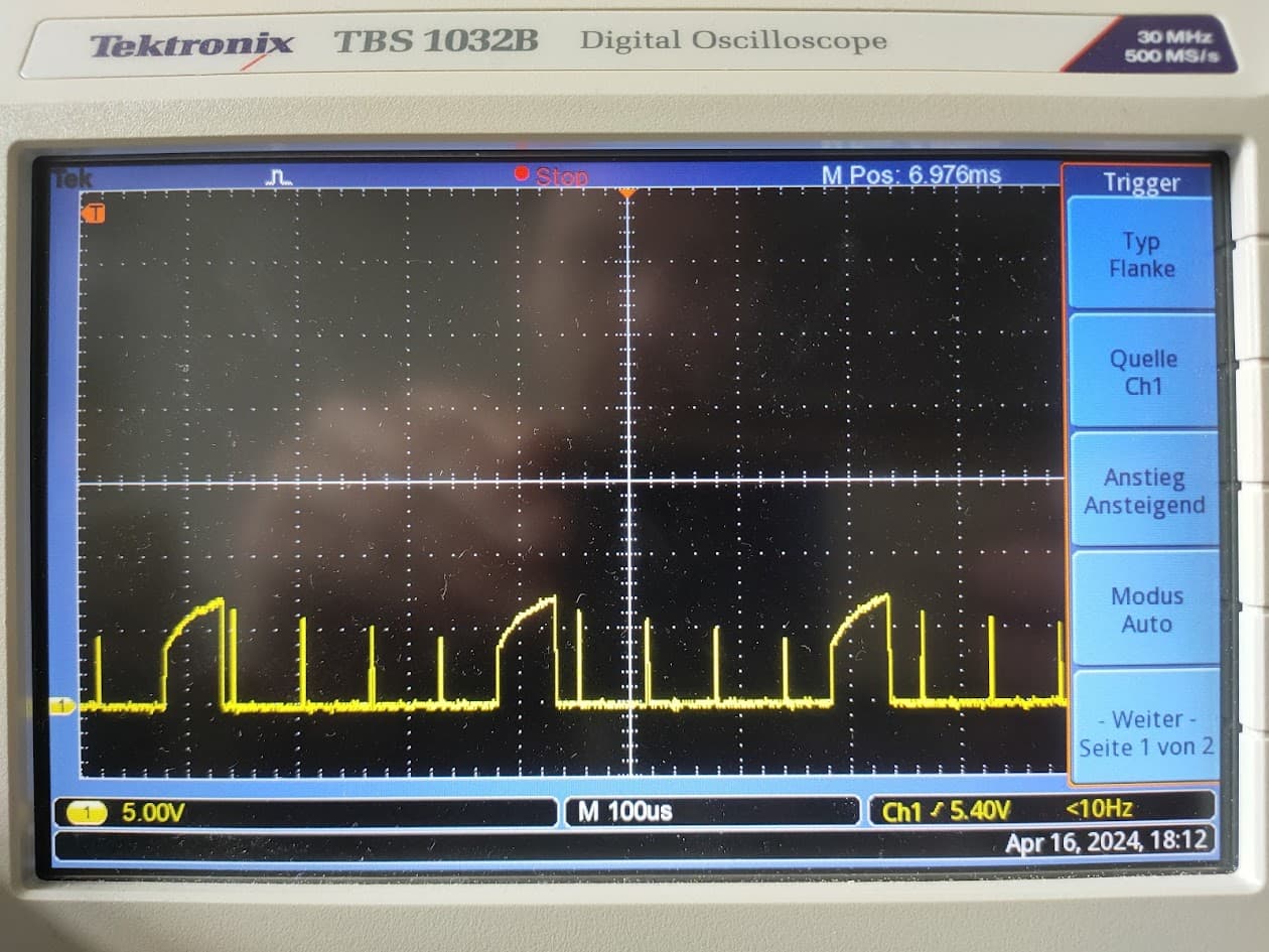
Does anyone have an idea about what is happening here?
Thank you in advance and kind regards,
c_animalstone
@c_animalstone Welcome to the community.
We have never tried this combination, so it might be hard to get help here. The qvardans was designed to work with simplefoc so you may have to dig and solve this yourself.
We are very curious to see if it works out. May be someone here has experience and could help you.
Cheers,
Valentine
Thanks ![]()
Ok, thank you for your answer. So I will go on and keep you up-to-date.
Hey there,
I paused testing STM Motor Control Workbench and went on with SimpleFOC - when this works, I perhaps will change back to STM. So far, I was able to read out the hall sensors and the encoder and to let the motor turn in open loop velocity mode with SimpleFOC. I used the example code files for these tests. Now I tried the voltage control example (for torque control with hall sensors), but this sadly burned my qvadrans, although the power supply was limited to 0.6 A. I assume, this happened because the resistance of the motor is only 0.293 Ohm and I didn’t set driver.voltage_limit = 12 and motor.voltage_limit = 4 as in the open_loop_velocity_example. Or what else could be the mistake?
I uploaded all code examples on GitHub - c-animalstone/qvadrans_simplefoc
Kind regards, c_animalstone
I’m no expert but I would guess the current limit on the power supply wasn’t fast enough to clamp the current before damage occurred. If the power supply voltage was set at 6v for example it would still try to pull 20A if there was no current limiting. I think this is why it’s typically recommended to use a low voltage limit / power supply voltage when testing with low resistance motors, even something as low as 1V or less.
Some of the limits on the library/code side can help this by limiting the output PWM duty cycle/effective voltage, but if those were not set or were not set correctly that wouldn’t help you here.
10 to 100 Ohm 100W power resistors based on your use case on each phase will do wonders to your test rig. Make sure you cool them enough. Only way to practically limit the current. It might sound primitive but it works.
Cheers,
Valentine
Hey guys, I’m looking at the design, and I don’t see any snubbing on the gates of the mosfets. I think the best hypothesis for the noise issues that one board had was the lack of snubbing. Don’t you think it would be a good idea here?
I am definitely no expert on this, but since the gate itself is a capacitor and you want to charge it fast with as little current as possible, additional snubbers are probably not desirable in this place.
They are common in this context, but it depends on the details. You do need to on/off the gates really fast. But the problem is the inductance of the leads going to the mosfet and the capacitance at the gate can lead to oscillations for some time after being “kicked” by the leading or falling edge of a high voltage square wave. I think. The result is that the mosfet turns on and off rapidly after you try to turn it on or off. Definitely not what we want. This appeared to be leading to short periods with the lepton 2.0 where the mosfet was supposed to be off but was still bouncing around and both mosfets on either side of the high voltage were on for very short periods. This created massive amounts of noise which messed up a lot of stuff.
I see there is the filter but I think addressing noise a little closer to the source might be good…
Not clear if this is happening, but I think it was happening on the lepton 2.0. I investigated, poking around with an oscope etc. However it depends on the lengths of the leads and capacitance of the mosftet etc, so we may not have that problem here.
In any case, it depends on the size of the resistors etc. that you use. There is probably an optimal which is harmless but useful. One option is apparently just to put a few ohms in series with the gate, but it’s usually combined with a diode in parallel with the resistor for some reason.