Are you using STLINK or DFU upload (no USB on Qvadrans)?
If STLINK: you need to have nRST (PG10) connected to the STLINK, it looks like it’s on a different header for the board than the SWD pins (PA13/14)
Are you using STLINK or DFU upload (no USB on Qvadrans)?
If STLINK: you need to have nRST (PG10) connected to the STLINK, it looks like it’s on a different header for the board than the SWD pins (PA13/14)
Yeah, Im using stlink with SWO, SCLK, nRST, GND, and VCC (3v) connected with my stlink V3Mini, & no usb on the Qvadrans. When i pull that pin to ground manually it resets, so im not sure why pio is having trouble there. Pretty much every time i go to upload it gets that failed to reset error. The ST-Link utility works without any problems most of the time, excepting the occasional error that goes away when i try again.
PIO doesn’t seem to use “connect under reset” by default, so the nRST is not used. The STLink utility can be configured to use connect under reset. So one works, the other (PIO) doesn’t.
Try looking here for a way to change the PIO script to use “connect under reset”
I found this:
So actually I guess the reset is actually set via SWD protocol, not pulling nRST low, unless you have “connect under reset” configured (you learn something every day!).
I don’t know why this works for me and not you - are you sure your STSTM platform in PIO is up to date? You can run pio update or pio upgrade from the command line and it should update some stuff, in case you’re running an old platform. Are you on Windows?
You got it again - my PIO core was up to date and I’d checked that before, but I missed updating my STSTM platform. After that updated, uploads work without any problems ![]()
my PR to STSTM platform for adding generic G431 was merged today ![]()
so it should be easier in the future to use this chip. No need for .json board files or any special config.
Finally got a good chance to take another look at the boards and got a motor spinning in voltage mode. Setting up current sensing for the first time is a bit over my head (at least for this week), but it moves! Just tested with a 7pp gimbal and AS5600 over i2c.
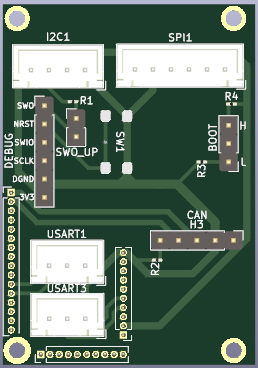
I also didn’t want to have to solder to the tiny pins a bunch so I made a breakout board with a reset button, connectors for I2C, SPI, and UART, and a header for the adafruit CAN pal breakout.
Unsure if everything on there will get used since this is the first PCB I’ve made, but it seems to work well from the limited testing I’ve done so far. Definitely makes things a bit easier to work with ![]() . It doesn’t use anything fancy like a ground plane/pours and it’s a 2 layer board so there’s definitely room for improvement, but if anyone wants the files for it I can upload KiCad/Gerber files on github.
. It doesn’t use anything fancy like a ground plane/pours and it’s a 2 layer board so there’s definitely room for improvement, but if anyone wants the files for it I can upload KiCad/Gerber files on github.
Yeah, I think that’s a good approach, so the board itsself is small but for dev work you get the breakout board… I do think I personally would prefer to have the connectors etc. on the board there even if it ups the cost but this is still progress.
Doesn’t the original board have space for headers (1.27mm pitch)? Why not just get some cables with matching pitch? I think you can buy these on Adafruit or similar.
I originally did solder some 1.27mm male headers and idc cable, but it was a huge pain to solder the idc cable to the headers. I also couldnt find any single row connectors that would fit on 1.27mm headers- 1.25mm molex picoblades are the closest thing i found after a couple hours of searching.
Since the idc cable was such a pain to solder I switched to using test leads for testing and moved to making a pcb. That way i could reduce the chance of wiring things up wrong and have a more robust solution if the boards work well enough to use four of them in the first test of a project. Definitely was worth it for me since the whole adapter pcb was quite cheap, but I’d love to hear if there’s an easier way to do it for next time around
Hi guys. I also want to play with this board, but an order of five pieces is a bit expensive for me))). I’d buy one board to experiment with from someone. I am in Austria, maybe there is such a possibility?))
The cheapest way is to buy the kits that let you assemble your own connectors with wires etc. pre-crimped. The pre assembled cables are ridiculously expensive.
For the little JST-SH connectors, pre-made cables are available cheaply on AliExpress. Same for PicoBlade connectors.
Such cables cost <$1 per piece, but of course you have to wait for them to arrive from china.
Are any snubber capacitors needed on the outputs to the motor?
I think snubber capacitors usually go on the gate of the mosfet? I don’t know why you would put them on the output of the motor. I did post a filter that I used which consists of capacitors and inductors to reduce noise, but very few people will care about that.
Hi @Pete_Bowsers,
We’re just getting started to use the QVADRANS board and are unable to find 1.27mm pitch jumper wires or connectors, could you share the schematic files or easyeda files somewhere?
With kind regards,
Zeno
Hi, welcome!
Ill do that.
Cheers,
Valentine
Thank you for the quick response but we’re looking for the files of the PCB that @Pete_Bowsers made, we’re unable to find jumper wires or connectors for the 1.27mm pitch headers. In EU we seem to only be able to find 2.54mm headers or connectors.
I possibly ordered something similar on aliexpress a while back. What I bought is out of stock but this looks the same:
I was using it to connect a stlink v3 STDC14 (1.27mm) which has both swd and rx/tx to a custom board I designed.
I realise this isn’t in the EU but it only takes 10 days to arrive typically.