Hi Valentine, Thanks so much for sharing your awesome designs! I’ve been looking for a cheap but capable board like this since I found SFOC and discovered that the footprint/connectors of G431 ESC1 boards could be a bit of a pain sometimes. I haven’t had the time to pick up designing and making my own boards yet, but your examples and comments are still really helpful and informative
I’ve got one question on ordering if you or anyone else could tell me if this is an issue or not: I went to order a few boards on JLC with assembly, and the M2 plated holes mentioned on the BOM (M1-M5) can’t be found as a component in the component assembly page of the order. Is this any kind of issue, or is this something that can be safely ignored?
Thank you. Ignore those but include them. Correct those are just board tricks we sometimes use to create special features on the boards that require no components .
Big thanks to you and @VIPQualityPost, much appreciated and boards ordered!
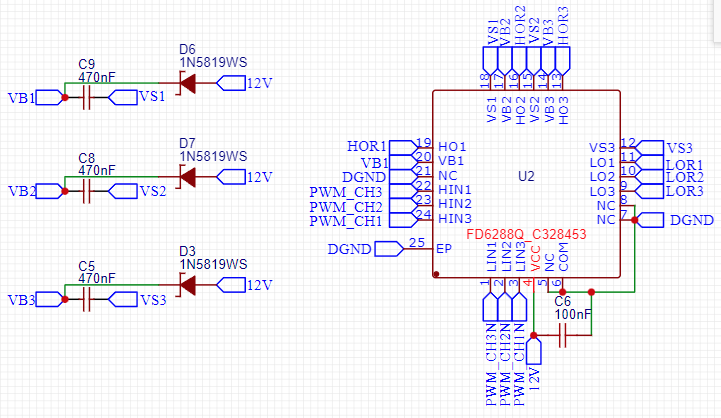
It’d be nice to be able to use a 3s lipo (cutoff of 9-10v) for a bit more convenient power on these boards or future boards since I’ve got a lower power application in mind, but I’ve never worked with gate drivers and am having a hard time deciphering the Chinese datasheet and operating principles for the FD6288Q (what I think is a gate driver?).
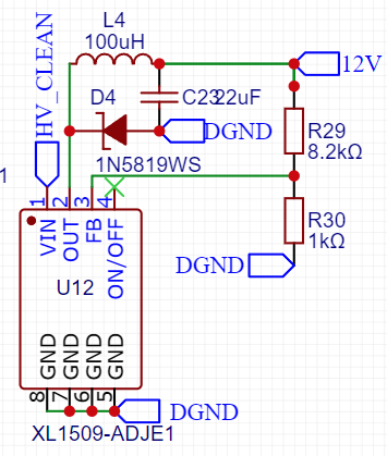
Is there anything I’m missing in the drive circuitry that would make it a bad idea to change R29 to something near a 7k resistor to get the regulator output around 7-9V instead of 12V?
You should check the XL1509 datasheet for the feedback resistor scaling ratio, but should be fine. Just double check your math before submitting anything.
It may fly, since the UVLO is 5V, however, you run up the risk of incomplete gate drive depending on your mosfets. I chose 12V as the best level to keep the gates operating properly.
One other thing, if you feed 9V, and keep the divider adjust resistors as is, you will simply get a voltage follower, and get 9v out of XL1509-ADJE1 anyways (minus some small drop due to resistance). Why do you want to artificially go that low to 7V and handicap the schematics?
Extreme case just get rid of XL1509-ADJE1 entire schematics and feed straight 9V or whatever input you got to the driver, as long as you do not exceed 18V. The driver will safely operate with VCC between 6V and 19V. Most mosfets will probably be fine around 7V, though I would not be doing this in a more serious application. As an educational exercise it will be fine.
The main reason I wanted it lower was that I was assuming the regulator would drop out entirely past its dropout voltage (13.5V?) instead of following the input voltage, so I wouldn’t be able to use inputs between 10 and 12V at all. I’m glad to hear that isn’t the case
One more question if anyone knows - is there a specific connector set intended for those headers, or any 1.27mm connectors that work well? I’ve never seen 1.27mm pitch connectors outside of IDC cables and I’m having a hard time locating anything else. Hopefully I’m not asking a bunch of dumb questions here, still pretty new to all this. Either way thanks to everyone for answering!
1.27 pitch is a 1/10 inch pitch standard header. It also matches the generic and widely used ribbon cable pitch (those flat rainbow cables you buy for a dollar). You don’t even need a connector, just a super steady hand and eagle eyes. And a good solder station.
This board is educational, you can change the connectors to whatever you want, some limited PCB design skills required.
Don’t forget I have not ever manufactured or tested the board. Maybe when I get time I will, so you take a risk here. Please come back and report your findings.
I’ve received my batch of boards and things seem to be fine with them so far (outside of accidentally sending 5V to the 3V rail on one board… ouch), but I can’t seem to get the PC11 LED to blink or a pin to flip from high to low. The power LED works just fine and I did manually short PC11 to 3.3v to check that the PC11 LED works, but it seems to be putting out a constant 0.3V instead of 0 & 3.3 alternating. Once the code uploads, I can’t detect any changing voltage on PC11, or on PC15 if I change the sketch to that.
When uploading a blink sketch with a digital write to PC11, I can get it to upload without errors after trying a few times (I’m guessing I’ve got a bad connection to the board, it’s fairly jank right now). This is using an stlink v3mini w/ SWD, SWIO, & NRST.
This was using platformio with the board definition for the ESC1 board, but since it wasn’t working I tried making board & variant definitions based on the schematic of this board and the definitions from the ESC1 board. Unfortunately that had the same results.
Anyone have ideas on what to look into next for this? Still pretty new to microcontrollers outside of arduino, so it’s definitely possible that I’ve missed something basic here
Is there any sign that the program is running at all? How are you powering the board? v3mini does not supply power by itself, just incase you’re not aware (I wasn’t when I first tried it).
Update - I indeed missed something basic. I forgot about pinmodes! Not sure why they aren’t getting set automatically like they seem to be with the ESC1 board, but once I set the pinmode manually the LED blinks.
@dekutree64 Thanks for checking! I did find that out after I tried uploading the first couple times
Yeah, ill try put all the variant & pio info up on github tomorrow when i get a chance. No guarantees that anything other than blink will work though I haven’t had a chance to test anything more yet
It’s on this repo. I haven’t had a chance to do anything other than the blink sketch yet, but when I test more I’ll put it up - I’ll probably start with I2C and UART before anything else. Let me know if you have any issues with it!
I’ve uploaded a fix to the variant pin definitions that gets Serial working w/ USART2. I had pins for USART3 as the default rx/tx the variants file but set serial 2 as the default… go figure. I tried using Serial3/USART3 on pins PB10 & PB11, but I haven’t found a way to get that working by editing the variants file or setting up Serial3 w/ HardwareSerial in main. I haven’t tried using USART1 or UART4 yet, so I don’t know if there’s any issues there either.
I also stopped being able to upload code using PlatformIO for some reason - maybe the linker script in there isn’t right since that’s copied from the STM32 ESC1, or the platformio.ini file needs upload arguments I don’t know about. I did find out that uploading built binaries with the STM32 ST-Link Utility is easy and that seems to work well, though.
The linker script should be the same for ESC1 and any board based on G431CB- maybe not that.
You shouldn’t need to tinker with the variant file - can you check that your platformio is set up right for this chip? For the G431CBU6 used on this board you should have these lines :
I figured there had to be something in PIO for a generic G431, but I couldn’t find anything online for PIO support of the chip outside of the ESC1 board. Is there an official list somewhere? I see that it’s supported by the Arduino core here but I haven’t had luck finding more about using a generic board with the chip, so that’s why I made the variant & board info.
When I try using board = STM43G431CB with or without that build flag I get an unknown board ID error from platformio:
Processing general (platform: ststm32; framework: arduino; board: STM32G431CB)
------------------------------------------------------------------------------------------------------------------------------------------------------------
UnknownBoard: Unknown board ID 'STM32G431CB'
Edit: I found the platformio stm32 registry & boards list and don’t see any generic boards on there - maybe they need to have only a custom board json? This thread seems to indicate that, so maybe it’s just the board json that isn’t setup correctly
Yes, I forgot about that file - here’s the one I’m using for my generic G431CBU boards:
I opened a PR a while ago in PlatformIO STSTM platform to add this file so the chip could be found by default but I guess they didn’t add it in yet.
Note: you may need to point PIO to use this file with boards_dir = <folder holding .json> in your .ini file.
Note 2: If you use this, make sure that you also put board_build.f_cpu = 168000000 or whatever your clock frequency is in - I put 170MHz because that’s the max but with most oscillators you would use in an actual board, the most you can get with PLL is 168MHz.
Thanks for sharing! That’s pretty much exactly the board file I was using / what’s in the ESC1 file. With that and the PIO args you put in earlier, USART1 works! PIO still can’t reset my board so that must be another problem, but I’m glad I don’t have to rely on fumbling around with a variant file I don’t understand