Since The Field Stack is powered up, its time to talk STM_Arduino_Core and how to make a Variant file for the project. @runger, you mentioned something about you have experience with this. If you can spare some time, and give some pointers that would be awesome.
I see there is generic_clock.c file in the folder. I suppose that is where all the appropriate clock configs generated by the STM_CUBE_MX should reside? Using a 24Mhz clock, I suppose we need to set that up in there. Maybe STM released some clock confiqs for the STspin32G4 Eval Board.
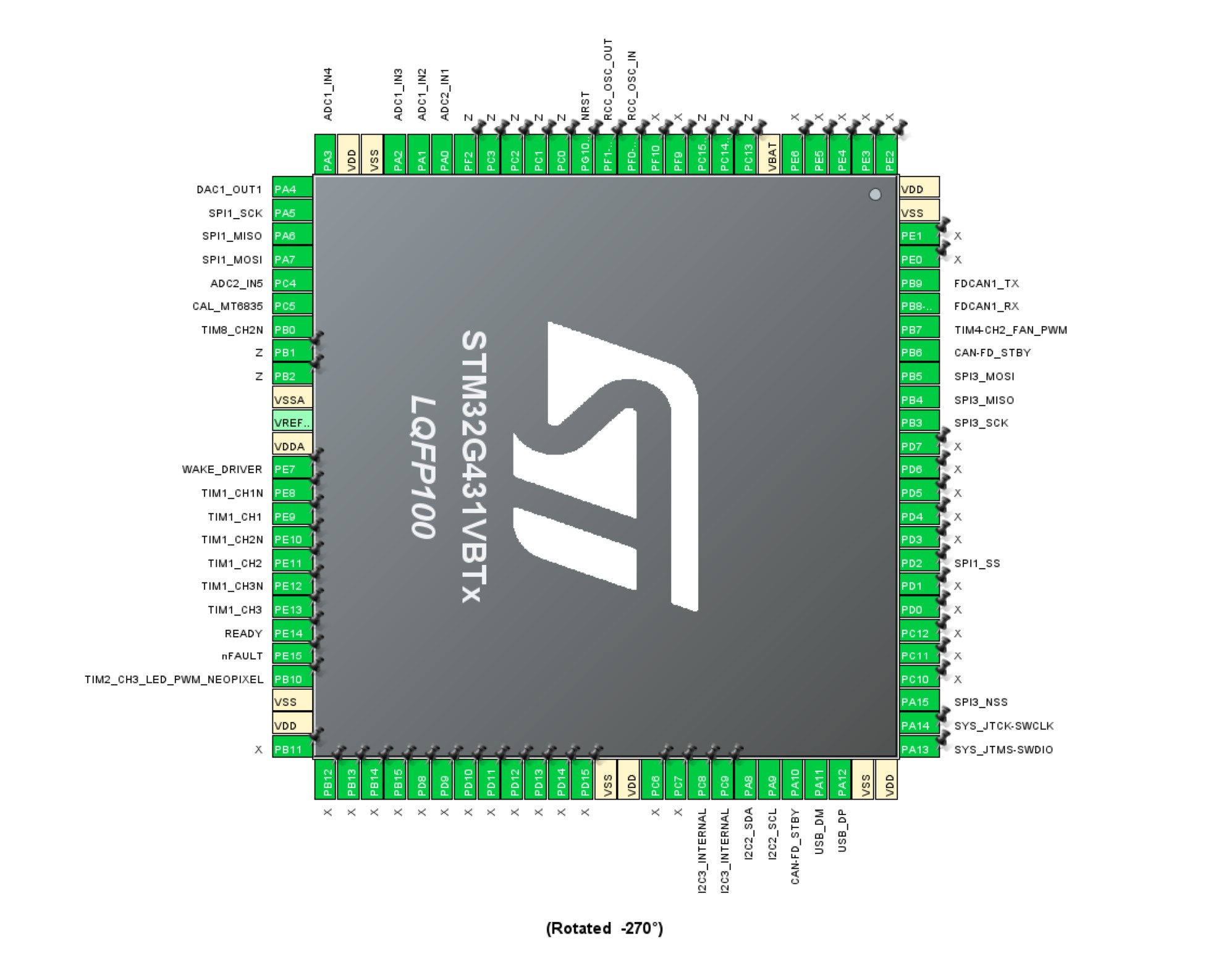
How can we specify the CAN FD pins and enable that feature?
Note: There is a small difference between MCU internal LDO voltage (3.3V exact) and the Analog Domain (3.29V), which is the one the ST-Link will read. I do not think it will pose a issue.
Are there any fuse settings we should be mindful of. Its my first time flashing a STM MCU, so I am not that familiar with the process.
I’m just getting to know PlatformIO. Making a ESC-G431 project now, and snooping around.
I see it created a STSTM32 directory with the boards folder. Supposedly that´s where the custom entry goes. Untill platformIO integrates the FOC SPING4 variant/board, I think it should reside in the repo with the schematics.
This was just randomly modified from the G431-ESC .json file in boards dir.
The Datasheet does say “The integrated MCU (STM32G431VBx3)”, so I am actually not sure “VBTx” is correct? Although it is the closest we get with STM32duino…
The clock is at 168MHz based on the external oscillator. Come to think of it, I didn’t check whether you’re using a crystal oscillator or clock source. One moment before you try anything
Not entirely sure how to configure the clocks yet. I think it should use the internal clock for sys_clock and the external 24Mhz for PWM generation ? Ill need to look into how ST does it with their Eval-boards.
Anyway, with a 24MHz external oscillator I don’t see any way to get 170MHz (max) out of the chip, best I could do was 168MHz. Don’t think the difference will be too painful, but still.
Seems 17MHz would be a good oscillator value to use. There also doesn’t seem to be a way that I can find to derive the USB clock (48MHz) from the external oscillator (24MHz) without significantly reducing the system core speed, which seems weird. But it has a dedicated 48MHz internal clock, seemingly for USB, so I’m using that.
Right, USB. I guess the only reason for flashing via ST-link the first time, is to set the nBOOT0 and nBOOT1 bit, to disable the BOOT0 pin and enable USB bootloader in the right mem-area? As I understand it, it comes with the bootloader already “installed”?
Edit: Or maybe that should be defined in the ldscript.ld?
Yes, you don’t have to do anything special for the boot loader, its built-in to the chip.
Via SWD and STLink, you can in normal circumstances just flash whenever you need to, no need to press any buttons. For the other methods, it can be necessary to hold down boot0 to get it into boot loader mode.
I’d recommend using SWD in the beginning, to eliminate a source of errors and problems.
Normally you don’t need to set any fuses, but it can be worth connecting with STM32CubeProgrammer (a free tool from ST) via the STLink. It will show which fuses are set and you can change them if needed.
Memory protection should obviously be disabled if you want to flash the chip.
You can set the bits to disable the boot pins, but that would only really be needed if you’re pulling it high I think, which you don’t seem to be.