I also just pushed some pin definitions in the header files…
Ok. Thanks again. Will try tomorrow. Its getting late here. See you at the ST innovation show !
Ok, ST-CUBE-Programmer installed and ready to go. ST-Link hooked up for the first time, ever. What a sweet little STM32F732 MCU. I love new nerd skills ![]()
Need to power the target w. 12V on the buck, while disconnected from the powerstage…
Not to say that I have abandoned the SAME51 completely. I still see great potential for the two (STpin32G4 and SAME51) to communicate over CAN FD or some stand-alone project. I guess it is a level-up to get some real STM32 experience.
Weird, I hope the internal oscillator is precise enough for USB. Apparently it is really finicky with timings. It would make sense to use the 24Mhz for exactly 48Mhz clock purposes? hmm
The way I read it they included the 48MHz HSI48 clock specifically for this purpose. It can be routed directly to USB, and if you use the main clock instead, then the best I can manage to configure is 144MHz system clock speed to get 48MHz for USB…
Let me know how it goes!
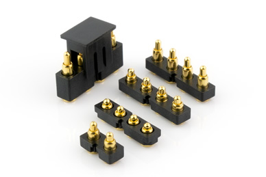
Those pogo pins are not pogo pins. On the mouser page it clearly says spring loaded. But the ones I got are in fact just landing contacts for the “real-pogo” pins. Is this some kind of grown-up teasing. Anyways. I made first contact with target after changing to 2.54mm headers on the ST-link adaptor.

I can read and change all option bits:


Are you making contact by pushing with a hand down on the bare leads?
Yes Contacts, I made contact with my own hands, robots will not replace humans, they just want to help and be friendly. Would you like a pad on the shoulder?
That depends… on the robot.
I could potentially sketch up a small 3D holder w. Spring loaded contacts. Maybe something that will clip on, so the target can be mounted on the powerstage.
I made this keyed spring-probe for SWD programming a few months ago. With regular PCB, it’s thick enough that you can mount a row of pins on each side and they don’t short. I just made a landing pattern that corresponds on the board - free connector ![]() the key (finger) fits into a small hole in the PCB that is part of the footprint. Assembly is a PITA though, getting the pins straight is hard and the pitch is too fine for any 3D printed guide.
the key (finger) fits into a small hole in the PCB that is part of the footprint. Assembly is a PITA though, getting the pins straight is hard and the pitch is too fine for any 3D printed guide.

Was inspired by this, which is too expensive imo:
But theirs has locking so you can leave it in the board for debugging.
Right, those are also relatively large. I’m thinking, I should have gone with something like these Yokowo ones. I believe it’s what’s inside my Garmin Forerunner clip-charger/usb cable. These come in 2mm and 2.54mm pitched
Unfortunately there is a large capacitor in the way, so it won’t be realistic to clip it on while mounted(on this revision). My initial thought was to flash once with the ST-link and then move over to usb.
@runger, regarding the USB clock to 48Mhz from external oscillator, it is possible by OC to 192Mhz core clock, but that would be somewhat outside specs. Perhaps later on…
Trying to set up the NEO-PIX like explained here: Controlling NeoPixels with STM32 - Embedded / Development Boards, Kits, Programmers - Engineering and Component Solution Forum - TechForum │ Digi-Key (digikey.com)
Using a CounterPeriod ARR value of 200 since the clock is twice as fast.
How can I generate the code for TIM2_CH4 setup from Cube_MX that will compile in the PlatformIO project?
Think I found a good guide here : Using STM32CubeMX and PlatformIO - FAQ - PlatformIO Community
hmm… I cant seem to choose GPDSC as toolchain?
I suppose it will be similar for the FAN PWM generation on TIM4_CH2 just with a different ARR (16bit TImer)
Maybe I should just try to dive into SFOC STM32 specifically and understand what’s going on with the timers. Also need to set up TIM8 anyway for 4th bridge. Has anyone experimented with TIM1 + TIM8 for 8pin PWM generation?
How can we determine if the 192Mhz runs stable?
This is the way?
So generating code for Makefile Toolchain and output .h/.c files for each peripheral.
For the fan you can use a 1-PWM based driver from our DC motor drivers (SimpleFOC DC Library, see GitHub). That won’t be a problem.
For the NeoPixel, driving those is not so easy and you should use some kind of finished NeoPixel library for Arduino with STM32 support.
Anything else will be a project by itself.
You’ll have extra difficulties if you try to use any instructions that aren’t geared toward Arduino framework. It is its own thing in the end.
But you also don’t need any other toolchain than PlatformIO + STM32 platform + Arduino framework. The project I shared on githib is already set up that way.
Don’t mess with that until it is working well within specifications… you don’t want to debug multiple things at once if you can avoid it.
No need for this. Arduino framework takes care of some of the peripherals, SimpleFOC (and other libraries) take care of the rest – if they have support for STM32 ![]()
Okay. still pretty impressive to see CUBE_MX output all that.
If I can just set up the timer and initiate the DMA like, transfer what CUBE_MX does, to the PlatformIO project. Then it seams relatively possible ?
It looks to me like Adafruit’s library should support it on cortex-m4:
https://github.com/adafruit/Adafruit_NeoPixel/issues/198
See if the Adafruit_NeoPixel lib doesn’t just work out of the box before you start coding your own driver…
Ok, so how does one include the lib into the PlatformIO project. In the .ini?
Like here:
lib_deps =
    askuric/Simple FOC@^2.2.3
    simplefoc/SimpleFOCDrivers@^1.0.2
Yep!
You can also use the UI to do it, by going to the Libraries Tab in PlatformIO, searching a library, and then adding it to a project.