PC817 as PWM Isolator

Hi All!
I am currently trying to create a board to drive BLDC and Stepper motor at something around 30Amps, but I am having a lot of issues with noise on sensor bus.
I would like to know if some of you has tried using this kind of optocoupler ( PC817) to isolate the logic of the circuit from the Power part.
I am currently doing some experiments and it seems to handle quite fine the Arduino PWM frequency (the opto should be rated 80khz, so it should be ok on Arduino PWM).
But, since none of the board posted on this forum has optocouplers in it, I started to overthink.
Is this a good solution? Or something bad could happen? (something that I don’t know and I am not considering)
Here the Opto datasheet:

Thanks!

80khz is rated for sin wave. Its not made for PWM. Its made for DC feedback loop.
Try something like 6N136.

1 Like

@Pipe

Which sensors and what are the issues? Have you identified the source?

Wouldn’t it be better to rectify the source of the noise rather than isolate the affected components?

Also, if you are decoupling a protocol sensor, say, SPI, you need a very high speed multi-channel coupler.

If you are decoupling analog signals, then your job is really hard, since you need to find a linear proportional coupler which are really tricky and relatively expensive, such as HCNR200 from Avago Technologies.

Good luck with your project.

Cheers,
Valentine

1 Like

Hello @Valentine and @hbozyq thanks for your help!!
Regarding Valentine questions, I am currently having issue with a AS5600 and a AS5048 through I2C, but also a strange behaviour with simple BLDC hall sensors (S49E).
My idea for this board is to drive either a BLDC motor either a Stepper through BTS7960B drivers.
My plan is to isolate completely the logic side, using a B0505LS for isolating the input voltage and using optocouplers to drive the power part of the circuit using PWM.
In this way the sensors that I will use will be directly connected to the microcontroller, that would be completely isolated from the Power circuit.
Has this any kind of sense for you?

Please forgive me if I repeat advice already given, but we get a lot of questions about the AS5600 and I lose track of whom I have answered in what thread…

Have you got the right pull-ups? Is the DIR pin on the sensor grounded (or pulled up)?
How many layers is your PCB?
Would you mind sharing your setup/pcb design? it could help a lot to see problems if we could see schematic/layout.

I agree with Valentine that it is probably better (and possible) to find the source of the problem than just to try to “isolate it away”…

@pipe,

Thank you. Just a disclaimer, I am not questioning or criticizing your design, only trying to understand the problem.

What issues are you having and have you proven with an oscilloscope and logic analyzer it’s real external noise that’s causing them? I2C is a very tricky protocol, it’s primarily designed for on-circuit communication, not over a wire (Inter-to-Circuit stands for I2C). Think at most a few centimeters. Using I2C outside the PCB over a wire will immediately create issues regardless of what your setup is. Perhaps using shielded twisted pair on low I2C speed over a short distance will fix your problem? Galvanic isolation won’t help.

More specifics please, if possible? I know many people work on proprietary designs, so I’m only curious.

Which input voltage, to the MCU I assume? B0505LS barely puts out 200mA. Why do you need that, if your MCU power supply is already designed properly? B0505LS are used in very niche, specific cases. Have you proven your MCU voltage is that dirty?

These are really old, discontinued drivers. They have slow response time to PWM. Be careful with them. Just a side comment, that’s all.

Cheers,
Valentin

Edit: One last thing, all IFX/BTN/BTS drivers have the same problem where the power ground is also logic ground, so you must take extra care to disconnect them. Have you done that? Else, you will get PWM output bleeding through ground back into whatever is connected. I believe in another thread I posted an MCU that burst because I didn’t do that, luckily that was just an experiment, and noone got hurt.

6.2 Layout Considerations
Due to the fast switching times for high currents, special care has to be taken to the PCB
layout. Stray inductances have to be minimized in the power bridge design as it is
necessary in all switched high power bridges. The BTS 7960 has no separate pin for
> power ground and logic ground. Therefore it is recommended to assure that the offset
between the ground connection of the slew rate resistor, the current sense resistor and
ground pin of the device (GND / pin 1) is minimized. If the BTS 7960 is used in a H-bridge
or B6 bridge design, the voltage offset between the GND pins of the different devices
should be small as well.
A ceramic capacitor from VS to GND close to each device is recommended to provide
> current for the switching phase via a low inductance path and therefore reducing noise
> and ground bounce. A reasonable value for this capacitor would be about 470 nF.
The digital inputs need to be protected from excess currents (e.g. caused by induced
voltage spikes) by series resistors in the range of 10 kΩ.

You should have a look at a couple of SMPS devices. There you can learn how to do it.
You need pulse-transformers. The 817 opto-coupler is only used for analog feedback-loops.

1 Like

Hello @runger,
The issue that I have with magnetic sensor is the one I explained in this post:

And you can directly see that on this video:

Yes I agree with both of you regarding the fact that I should face the problem and not hide away from it, I am just curious to see if this “overkill” solution would give some results! eheh
Regarding the AS5600, for now I am evaluating that using this ready board:

It should already have pullup resistors on board, so I didn’t added any other.
I saw your previous posts in other threads, I am currently using a setup with Arduino Uno and somewhere you wrote that it (in theory) it should not need pullups for I2C.
In theory, from that side I should be covered.

My board design is currently just double layer, I don’t have size constraint this time, so I can adapt to the best solution possible you suggest (even if it is a single layer one).
I will post the design in the next days!

@runger @Valentine both of you have said that I2C suffer when used with cables, should I use another protocol that this magnetic sensor are providing me? I know that SPI is worse noise wise, I think that what remains is PWM, I never used that sensor using this protocol but I saw that you have created an implementation in the SimpleFOC library for that, what are the advantages and disadvantages of using PWM in this specific case?

Regarding the B0505LS as I said before it was just for overkill the Isolation, currently my MCU power supply is a combination of a 1000uf low esr capacitor, followed by a 100nf ceramic one, then I prepare the 12V power line (that I need for other things not yet implemented) with a SRH05s12 which output then goes into a L78L05ACZTR that goes to the MCU, between the 5V and the MCU I wanted to add the B0505LS, but I am no more so sure that this is a wise choice.

@Valentine regarding the Drivers, I used that exactly in the way I see in the Layout Considerations you quoted.
I am completely aware that they are obsolete, but I really can’t find a similar solution that is available in component stores this days…
(for this, I planned to buy a stock of these: Double BTS7960 and unsolder the drivers for my boards (so as you see I am desperate).
I saw your project:

But the drivers that you used are not available, anywhere…
Keeping in mind that I don’t have board size constraint, and I need to reach similar specs of the previous drivers (but with a modern and more reactive solution), do you have any suggestion to something that could be easily retrieved?

Finally regarding the S49E, weird things happens, if I load on the board the SimpleFOC Hall Sensor test Example and I move the BLDC motor it works fine, but then If I load another example where I try to move the motor, such as the open loop one, when I load back the Hall Sensor example If I rotate the rotor by hand as before, the debug value wiggles between 2 values and it does not move from 0, this happens for 2 or 3 minutes, then it goes back to normal (anything changed on the board, just the firmware, this is extremely strange).
I have a 10k resistor pullup for each one of them, and while they retrieve “corrupted” data I tried just to debug also the DigitalRead, and what I see there seems correct…
Obviously when I try to use the closed loop, I face strange behaviours.
Do you have any advice about this? Am I doing something wrong?

I will post the complete board schematics in the next days, for now Thank you so much for your help!

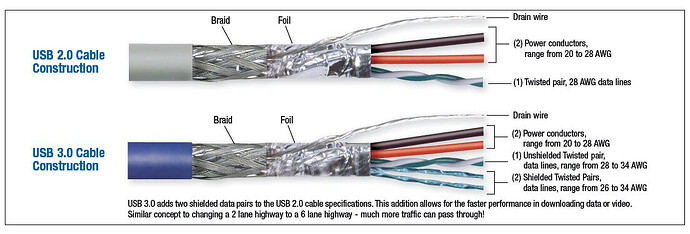
Not true, I’ve used SPI over about a meter with a high quality (high twist), shielded and grounded cable. There were few other threads here where this was discussed in excruciating details. I use it with the AS5047 sensors.

Edit: Hint: get a high quality shielded USB 3.0 cable and use it for SPI. Some wire cutting/stripping and assembly required. It’s perfect. You have the four data lines, and separate power and ground, and extra shielding.

Oh Nice! Thanks for the tip!
Could I try to use a Lan Cat6 cable! It should be veery similar (but easier to crimp) what do you think??
@Valentine do you any suggestion on the drivers, it really seems that everything is unavailable or discontinued these days.
For example, it would be a good idea doing H-Bridges with some mosfet like the IRFB7740PBF?
Thanks for all the explanations and tricks again!

how about shielded Cat.5 ethernet cable? It might work nice aswell but cheaper.

Cat8 is then what you want. Each tp is shielded individually. They are thick and hard, however, and bulky. If your setup is stationary cat8 is an excellent choise.
Let me check the mosfets.

It may. Depending on the distance.

This is a recent thread.

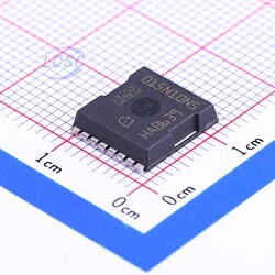
Discrete mosfets have never been in shortage. Challenge is to design the board, as they require drivers and an MCU to drive them. Any mosfet would work. If you need high voltage, high current mosfet, there is one I really like, it’s available for SMT, you don’t have to burn your fingers soldering it:

JLC part number C108964, 300A / 100V

If you are not constrained for space, this is the sledge-hammer that could drive a 12-inch nail spike into a railroad tie. Six of those could power a golf cart.

1 Like