maybe I misunderstand something, but I thought, if I repeatedly call motor.setPhaseVoltage(U, 0, Angle) with small, increasing values from 0.0 to 6.28 *polepairs, for Angle, the motor should turn exactly 360 degrees. In my case, this is not happening, instead of 6.28 rad (=360 deg), the motor turns reproducible 6.39 rad. Cw or ccw doesn’t make difference except for the sign of course. I compare the values to the sensor readings and verfied that the sensor is correct, it is the motor which is wrong.
Here is the essential part of the code (sorry for the messy code, it was wildly copied and pasted together):
void Turn360Deg(int Direction)
{

  const int n_ticks = 64*POLEPAIRS;                                   // number of positions to be sampled per mechanical rotation.  Multiple of NPP for filtering reasons (see later)
  const int n2_ticks = 16;                                        	// increments between saved samples (for smoothing motion)
  float deltaElectricalAngle = _2PI*POLEPAIRS/(n_ticks*n2_ticks);      // Electrical Angle increments for calibration steps
	float elec_angle = 0.0;

  //Set voltage angle to zero, wait for rotor position to settle
  // keep the motor in position while getting the initial positions
  motor.setPhaseVoltage(UALIGN, 0, elec_angle);
  _delay(1000);

  sensor.update();
  float initialAngle = sensor.getAngle();
  Serial.printf("Initial angle = %.2f\n", SensorDir*initialAngle);

  Serial.println(F("Reached zero position, hit any key to proceed!"));
  while (!Serial.available());
  while ( Serial.available()) Serial.read();

	if (Direction>=0)
		Serial.println("Rotating 360 degree ccw");
	else
		Serial.println("Rotating 360 degree cw");

	int k = 0;
	for(int i = 0; i<n_ticks; i++)
	{
		for(int j = 0; j<n2_ticks; j++)
		{
			elec_angle += (-Direction) * deltaElectricalAngle;
			motor.setPhaseVoltage(UALIGN, 0, elec_angle);
		}

		// delay to settle in position before taking a position sample
		_delay(3);

      sensor.update();
      float Angle = SensorDir* (sensor.getAngle() - initialAngle);
      Serial.printf("%.2f\t%.2f\t%.2f\n", elec_angle/(float)POLEPAIRS, Angle, elec_angle-Angle);
	}
}
Some more facts: B-G431B-ESC1, T-Motor G60 Kv55 (14 pole pairs), AS5147 in SPI mode (yes, no typo), latest SimpleFOC 2.2.3
Why don’t you use position control to move the motor 1 turn?
That is how I started (with example code for the alignement and cogging test). Since I could not explain anymore what I saw, I tried it in a different way. Same result unfortunately, but that tells me that the test program as such is correct, maybe my motor definition is wrong or so, but what could have this effect with a 14pp motor and result in 0.11 rad difference?
Open loop works just fine, but closed loop does not, despite all tuning. That’s why I investigated into the details and found that there is a difference between the mechanical and the electrical angle. To my understanding, Closed loop will never work right if that is the case.
Yet another observation which might steer someone towards a solution: The electrical offset angle changes whenever I start the program. I recorded some values and it appears to have some regularity. The first vallue was 4.9, then it slowly decreased monotonic to 0.42 and from then on increased again monotonic up to 3.32, where I stopped. In total I recorded 10 values. Mystirious. I hope it is just a stupid bug on my side, but can’t find anything.
0.11 rad is approximately pi/28, so for a 14pp motor (28 rotor magnets), that should be 90 electrical degrees, or the difference between stopping centered on one magnet or half way between two magnets. Seems like setPhaseVoltage must be where the problem is occurring. Maybe just print out a big sprawl of elec_angle and corresponding Ua, Ub, Uc values throughout the rotation so you can see if it’s a gradual drift or what. Also try making a second lap and see if you’re still only off by 0.11 rad or if it goes up to 0.22 or something else.
I’d also say it should be on the sensor side, since the spi sensors are abolute ones and you should always record the same electric angle ( approximately ), at least when using the motor.initFOC().
Did you try to verify vosually that this offset actually happens?
Like, instead of 1 round do 5-10 rounds and you should see the error augmenting. It should quickly become visual.
Also many people have issues with magnets slipping in the mount, this could explain the moving electrical angle behavior.
Yes, the offset is clearly visible and in line with the sensor readings (as far as one can visually tell). Since it is open loop, the sensor should not have any influence on how far the motor turns, right?
It is getting interesting… First of all, please excuse, my previous post was probably wrong. Depending on which test routine I use, I obtain very different results.
If I use the alignment_and_cogging_test example code as the basis, which uses motor.move(), then I get a clearly visible difference between the target motor end position and the actual position. I do not trust this anymore however, since the motor makes unusal noise during the first step of the rotation, as if it would reposition itself again after having been set to 0 before. Needs to be investigated deeper, maybe a bug in the test program (this is all true for my modified version of the example code, not saying anything about the original example!).
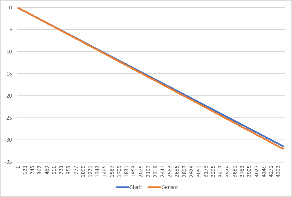
Now, with the code listed above, which uses setPhaseVoltage(), the movement is very smooth, right from the start and I obtain a nice, linear relationship between sensor and shaft, but the shaft lags behind, not the sensor as I observed with the other code. Also, the difference is far smaller. Here is a plot over five turns:
Honestly, I trust the Turn360(9 function from above more than the alignment test at the moment, since it is more basic and low level, so I will stay with that for now. Anyway, that brings me back to the sensor as the real problem. If the magnet slips as @Antun_Skuric supposes, this might be an explanation, but the the direction is wrong and I would expect the error to be less systematic and more erratic.
How would a sensor misalignment manifest itself? Would it not be a cyclic error, which is zero on average over a full turn?
Yep, that’s weird alright. By all logic it should be impossible. Sensor::update calls getSensorAngle, which returns (getRawCount() / (float)cpr) * _2PI. So that should give a cyclical error if anything. That value is stored directly to angle_prev so no possibility for error there. And full_rotations is stored as an integer so it can’t have any gradual drift. I suppose you could verify that cpr is correct since it is a float and therefore the only possible source of drift I can see.
Checking on the T-Motor site, it doesn’t show what the inside of that motor looks like, but I did find this which is probably the stator/magnet ring set used. Indeed 28 magnets/14pp, so I think we can rule that out.
Have you tried attaching a pointer to the motor to verify that it’s physically oriented exactly the same before and after the 5 rotations? EDIT: Nevermind, I don’t think it will be due to the way the test code increments elec_angle repeatedly. Numerical errors will accumulate and you won’t end on an exact number of rotations. However the elec_angle and sensor angle should still match.
Just out of interest I suppose you could try calculating elec_angle fresh every time and see how the graph looks. Instead of elec_angle += (-Direction) * deltaElectricalAngle, do elec_angle = (i * n2_ticks + j) * _2PI * POLEPAIRS / (n_ticks * n2_ticks)
That should land you on exactly a full rotation point (actually a tidbit less since j will be one tick short on the last iteration, but close enough)
At least, I think i understand, why the electrical offset changes. Could it be, that the starting position of the absolute encoder is never taken into account? The sensor could start at a different position each time the program starts. BTW, I am using the class MagneticSensorAS5047.
Have you tried attaching a pointer to the motor to verify that it’s physically oriented exactly the same before and after the 5 rotations? EDIT: Nevermind, I don’t think it will be due to the way the test code increments elec_angle repeatedly. Numerical errors will accumulate and you won’t end on an exact number of rotations. However the elec_angle and sensor angle should still match.
Yes, I did, that is how I checked if it is sensor or the motor.
The starting position of the encoder does not matter - during initialisation the motor will be aligned with the electrical zero angle, as determined by the current sensor value at that time. So since a 14 PP motor has 14 electrical revolutions, my understanding is there could be up to 14 positions it should return as the zero angle.
Your problem with the angle is a strange one. The way it looks I’d say the sensor leads or “is ahead of” the motor, as it seems to have opposite direction to the error when you start it down counting than when up counting. Its the behaviour I would expect to see if you set the CPR parameter of the encoder class too low by one or two ticks. then each actual revolution of the motor would produce more ticks than expected.
But you say you’re using the MagneticSensorAS5047 class and SPI mode, so that’s not the case here. The CPR looks to be set correctly to me, 16384 and on looking over the code and the AS5147 datasheet I see no reason why the driver should not work on this sensor, at least for reading angles… I didn’t check the other registers.
The sensor has a “dynamic angle error compensation” feature. By default the code reads the uncorrected angle, but you could change it to read the corrected angle, and see if this helps any?
I can’t really see anywhere in the code where we would introduce an error of one, so at the moment I’m with the slipping magnet or sensor error faction. I’m interested to learn though what the problem turns out to be.
I’m running out of ideas to prod it with Here’s one though. At some point in the loop, add POLEPAIRS * _2PI to the elec_angle and see if either the phase voltage Ua Ub Uc or the sensor angle jumps suddenly. It should have no effect due to the call to _normalizeAngle in setPhaseVoltage. If it does have an effect, try outputting the return value of _normalizeAngle(elec_angle) before and after the addition.
I played a bit with the CPR, but the effect is (too) marginal, which I find suspicious. I need to investigate this closer, but I am running out of time for today.
I think so too, and I can read all registers. I also tried to read the compensated angle, made no difference.
The error is so systematic and turning back and forth results in (close to) zero error, so a magnet slipping problem sounds very unlikely. I learned however, that if you can rule out the likely causes, it must be the unlikely or “impossible” ones. Let’s see.
I tried this, no change.
Tomorow I’ll investigate more into the CPR setting and then I will disassemble everything, play a bit with the magnet distance and try another sensor.