Excellent, that rules out a lot of possibilities to worry about.
Next test, disable the driver and turn the motor several revolutions by hand and see if the sensor angle still accumulates error. e.g. make exactly 5 turns, and see if sensor.getAngle() - initialAngle is exactly 10pi or not. That should verify that the driver code is not involved and it’s purely a sensor problem.
If it does still accumulate error, output Sensor.getRawCount() and continue making manual turns. Check the value each time you pass the starting point. I don’t see how the sensor could “remember” that you’ve made multiple turns and output a different value for the same magnet orientation, but that seems to be what’s happening. I’m starting to suspect a faulty sensor.
Even after only one round it is clearly visible that the sensor counts faster than expected.
Apart from that, the sensor seems extremly reobust against misalignments. Only after completly misadjusting it, I got the following curves (two revolutions forward and two backward):
I cannot measure it, but the misadjustment was really a lot and the sensor distance between sensor and magnet is at least 5mm, all way out of spec.
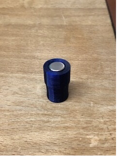
Now the good news: I am 99% sure I found the problem and @runger was right and the very unlikely became true, I have a slipping magnet. The bad guy is this:
It is 3D printed from PETG and when I installed it, it was a nice pressfit in the hollow motor shaft. Apparently the PETG shrunk with the heat of the motor and it became so loose, that the magnetic force was obviously strong enough to let it slip. It shrunk so much that even glue would probably not stick anymore. I still do not understand how this can be so regular and revert to zero after reversing the direction, but perhaps this is somehow related to the magnetic field of the motor itself, I really don’t know.
I am however not sure how to proceed. PETG is certainly no more option. I have some polycarbonate here which is supposedly more heat resistant and I could print with 100% infill, but I am not sure if this is sufficient. Any experiences here? Metal is possible for me too, but that would be a least resort since I need someone to help, I haven’t used the machines for 40 years now…
What really annoyes me is that I bothered you all and the solution is so simple. It was however not visible without disassembling everything and that is quite some work and a bit delicate to not break anything. Please excuse and thanks a lot for your thoughts! In any case, I learned a lot again.
Wow, that is surprising! But good to know that the code really is simple enough there’s almost no way for it to introduce errors And that magnets can slip in improbably repeatable ways.
You could anneal the PETG to get the shrinking out of the way before fitting it. Crush ribs are a good way to do precision fitting by hand, because you can see how much you’ve removed from each one to keep it concentric. Plus it gives you a little more leeway between when it won’t fit at all and when it’s too loose. And if you can get glue to stick to the inside of the shaft more strongly than it sticks to the magnet holder, it will function as a spline even if it does become loose.
Another potential material would be some moderately hard flex filament, so it can compress a bit and will take more shrinkage before it becomes loose.
I think is actually expected to be very much repeatable since the movement is rotation (repeatable) and the gravity is the main pulling force that the magnet is being subjected to (a constant) - so you do have repeatability after each turn since the gravity is constant, and the rotation itself is a repeatable movement. Other forces would just create smaller deviations on the repeatability.
Hm, it is all rotational symmetric and the axis is horizontal. I can‘t really see where gravity could cause a significant rotational force here. I suspect more a magnetic effect and since near the magnet it is all plastic or symmetrical again, I suspect the magnets inside the motor. Inductivity can be excluded since it happened without feeding the power rail as well. It was really surprising, you should have seen it. I could spin ten turns back and forth and the accumulated error was close to zero again, as if friction was very low and constant.
You are actually right - the magnet will always be pulled to another magnetic field on the rotor (depending on the distance and mag field strength) and often even pushed by the magnet on the oposite side.
For some reason (I have no idea why), I though the magnet had plenty of space to move around. In that case, centrifugal forces + gravity could create a similar effect depending on the speed of rotation.
So, everything fine now. I have printed a part using PC and 100% infill.Error is now alweays <0.02 rad. I will run a test over some days and see how it behaves. I will also include the sensor test in the startup code of my project, to make sure that I detect sensor problems after a lonfger time too. With the slipping magnet I am also not surprised anymore that my ESC blew up.
Have a nice weekend and thanks again for all the advice,
Chris
BTW, I made another interesting discovery, the sensor itself seems to lag a bit in its measurements. It looks as if there was some kind of control loop or so built in and certainly there is some delay caused by the sensor internal processing. It is surprisingly high though. In the diagram below you see in blue the mechanical position and orange the sensor position in rad. Between each step there are at least 3 ms plus code execution time (printf takes long…). I expected the sensor to react faster to position changes. Fotr me that’s no problem, but in other applications this might be critical. I used the raw position as returned by the class MagneticSensorAS5047 per default.
If I do the same, but reading the compensated value, the delay is even worse, but I only tried one run and created no real statistics on it, so no scientific investigation.
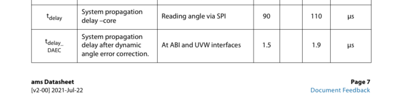
The propagation delay from the datasheet is a very different order of magnitude than what I observed. I think so that my interpretation is totaly wrong. It is more likely the motor has not yet reached stable position than that the sensor has such a long delay. I just modify my test routine to take that into account.
Wow, it takes up to some 10 ms until sensor readings become stable, but timings vary significantly. The average is something like 15 ms. I take 64 samples per electrical rotation (waiting for stable reads at each sample) and in between there are 16 steps where I just set the phase voltage and don’t wait for anything to settle. Should I ever write code for something which requires very accurate positioning, this is certainly something to take into account.
If it is a constant factor/variable, then it’s a matter of defining the lag, I suppose.
Does your SPI interface use DMA. I’m no expert in ST MCUs and maybe there is no real gains in DMA transfers since the data is quite short/small amount. It would be interesting to compare though
Are you using the sensor in “fast mode”? Or normal?
Are you plotting the value from the sensor directly, or the value from after the LPF filter?
When running in open-loop mode you’re just rotating the magnetic field, and “dragging along” the rotor hoping it will follow… you can expect a certain amount of “lag” between the commanded value and the actual position, and a “settling time” as you put it, when the rotor catches up to the field after you stop commutation.
I suppose the amount of “lag” will depend on things like physical motor properties, commutation speed and the voltage applied.
All this is of course significantly improved in closed loop control.
I read the sensor position several times with a short pause in between untill a number of consecutive readings have a very small and expected difference only.
Very good point! Unfortunately I can’t test it easily, since my tests are all so low level. I need to think about how much changes are required to test in closed loop.On the other side, what I have now is exactly what need with regard to the test routines. Everything else would just be plain curiousity (but isn’t that what drives us all?).
From my viewpoint, if the sensor readings are useless, then the sensor is worthless. That may be too idealistic, but how many iterations does it need for a good enough result? It sounds to me, that you are trying to compensate for a noisy sensor and in that process you are seeing the lag. If we have to predict the angle sensor result, that kinda defeat the purpose of having the sensor. This just adds to the propagation delay challenge.
I know it’s too early to conclude anything about the MT6835, but I have my hopes up.
FYI
One jitter problem I’ve had similar to what you’re describing was related to sensor wire harness EMI. I was using unshielded jumper wires, and simple moving the wires around made the encoder signal go from tons of noise like you’re showing, to perfectly stable. Motors were uncontrollable and the temporary fix was to empirically tape one of the wires away from the rest. It worked rather well, but shielded cable might help. I’d move the sensor wires in question around and see if it affects the signal. It was the same result with multiple harnesses, so I don’t think it was a loose wire problem.
Don‘t worry, I am very sure the sensor is working fine and fast. It is the motor which has to reach its position and then has to stop there to have consistent readings. If I don‘t wait with the readings, the error gets slightly bigger, but that is a fairly constant lag (-> @runger ‘s post above). The actual sensor noise which I see is more like +/-2 increments. EMI is no issue as far as I can see. Since I am using SPI, I would expect values due to EMI which are very random and cause large errors. With ABI interfaces it could of course be very different.
As Mechaduino has documented with their calibration-look up routine (above link) the non-linear error of the AS5047 is a real thing. For closed loop control or commutation purposes of a BLDC with low “step” count it may not be an issue, but surely a more precise sensor (0.07 non-linear error when calibrated w. Basic routine MT6835) will produce better results.
If you are able to test the effect in closed loop, we can compare sensors, which will be a valuable asset.
Edit: I must admit, the Mechaduino link does not say, if they are using the, at the time, new AM5047P with dynamic angle error compensation. I suppose the standoff really is about how reliable this feature is ?
Ok the AS5047U is apparently even better. Pardon my ignorance on these sensors. Always great to learn.
So which one are U using ? Right, U did write the AS5147, I think I’ll just be quiet for now