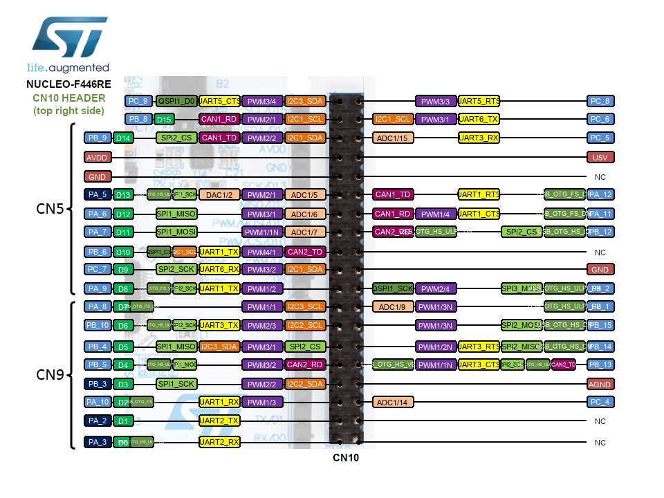
first I tried connecting it to (PA_5, PA_6, PA_7, PB_6) exactly like in the pic on the driver page , when that didnt work i changed it to TIMER1 pins as pasted above
I changed the motor voltage limit from 10 to 15 to 20 (its supposed to run on 20) in case it had any effect, but it did not.
I even set float target_velocity directly in code to 0.1, 0.5, 1, and 2, in case it was a problem w the serial, no effect.
The serial monitor reads “Motor ready! Set target velocity [rad/s]” when powering on, so setup() seems to run fine.
Green light on the mini lights up when powered and its not overheating (i have a thermal cam) so I dont think I fried it.
Im at a complete loss and willing to try Anything at this point.
Target mcu is set correctly, ive been running other sketches w/o issues.
I dont have a scope but ill have access to one next week, ill record all the pins and post them here, but itll be a few days.
Arduino IDE 2.1.0
code is open_loop_velocity_example found in Examples → Simple FOC → motion_control → open_loop_motor_control → open_loop_velocity_example
> // Open loop motor control example
> #include <SimpleFOC.h>
>
>
> // BLDC motor & driver instance
> // BLDCMotor motor = BLDCMotor(pole pair number);
> BLDCMotor motor = BLDCMotor(11);
> // BLDCDriver3PWM driver = BLDCDriver3PWM(pwmA, pwmB, pwmC, Enable(optional));
> BLDCDriver3PWM driver = BLDCDriver3PWM(PA_8, PA_9, PA_10, PA_5);
>
> // Stepper motor & driver instance
> //StepperMotor motor = StepperMotor(50);
> //StepperDriver4PWM driver = StepperDriver4PWM(9, 5, 10, 6,  8);
>
>
> //target variable
> float target_velocity = 1;
>
> // instantiate the commander
> Commander command = Commander(Serial);
> void doTarget(char* cmd) { command.scalar(&target_velocity, cmd); }
> void doLimit(char* cmd) { command.scalar(&motor.voltage_limit, cmd); }
>
> void setup() {
>
>   // driver config
>   // power supply voltage [V]
>   driver.voltage_power_supply = 24;
>   // limit the maximal dc voltage the driver can set
>   // as a protection measure for the low-resistance motors
>   // this value is fixed on startup
>   driver.voltage_limit = 20;
>   driver.init();
>   // link the motor and the driver
>   motor.linkDriver(&driver);
>
>   // limiting motor movements
>   // limit the voltage to be set to the motor
>   // start very low for high resistance motors
>   // current = voltage / resistance, so try to be well under 1Amp
>   motor.voltage_limit = 20;   // [V]
>
>   // open loop control config
>   motor.controller = MotionControlType::velocity_openloop;
>
>   // init motor hardware
>   motor.init();
>
>   // add target command T
>   command.add('T', doTarget, "target velocity");
>   command.add('L', doLimit, "voltage limit");
>
>   Serial.begin(115200);
>   Serial.println("Motor ready!");
>   Serial.println("Set target velocity [rad/s]");
>   _delay(1000);
> }
>
> void loop() {
>
>   // open loop velocity movement
>   // using motor.voltage_limit and motor.velocity_limit
>   motor.move(target_velocity);
>
>   // user communication
>   command.run();
> }
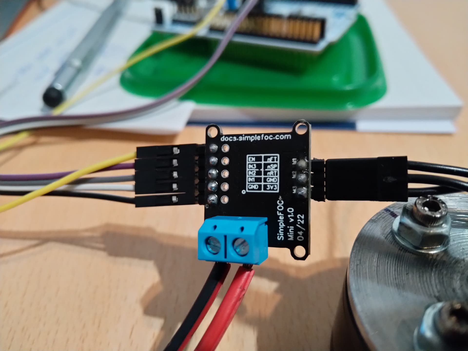
Hmm… don’t see any problems. Could you please post hi-rez pictures of the setup, with the motor, and the wires clearly showing? I want to make sure you connected everything properly. Taken from different angles. I want to verify your wiring setup.
I only see one 5 volt power supply, but the voltage of the driver in min 8 volts? If you can check with an led and a resistor to see if the pins of the mcu are doing anything that resembles what you want. Always, the proceedure seems to be to get in there and follow the flow of the operation of the system.
Also you should actually set the power supply voltage to what the power supply voltage is, and don’t forget to change the max voltage to the motor to more like 1 or 2 volts, that’s the peak to peak voltage actually sent to the motor, in open loop mode
No, the power supply voltage is 24v and the voltage sent to the motor controls how much current you push into the motor, you will burn the motor if you max out the voltage. Start out with low voltage, say, on a 24v supply send about 5v, this will be enough to free-spin the motor, and velocity around 5 rad/s.
I’ve used similar motors a lot, the 20 volts means next to nothing. You have to go by how much current is being drawn and how much mechanical power is being output, the difference is waste heat, and it only takes a few watts of waste heat over some time period to make things a little to hot for comfort. I can think of a lot possibilities for things that could be going wrong here, but the only useful advice really is to measure everything at every stage to isolate the fault… another possibillity for instance is that a ton of current is getting pulled when things switch on and this causes the power supply to shut off. I’ve had that problem with these types of power supply, if it’s a wall wart.
Also yeah you are quite right to be careful about those screws, I have destroyed more than one motor by accident. It takes very very little excessive torque on the screw after it touches the coils to break the wires on the coils.
How is this possible, the way you connected it, yellow is GND, not A5. You connected yellow enable right next to AVDD. You need to connect enable yellow to A5 which is one pin down from where it’s connected now. I believe you are driving the enable low and putting the driver to sleep. Move the yellow out of fifth GND pin (counting from the top) and connect to the sixth pin which is A5.
Also, why is black (GND) connected to AVDD? Black goes to GND (5-th pin). Seems you off-ed your connection by 1, hope you didn’t blow your driver by connecting AVDD to GND on the driver board.