Any progress?
Cheers,
Valentine
Any progress?
Cheers,
Valentine
Hit the daily post limit for new users, had to wait 19h to reply.
Thats exactly what I did. ![]() I assumed they were parallel to the pins on the left, thats embarrassing.
I assumed they were parallel to the pins on the left, thats embarrassing.
Just wired it correctly and plugged in a new unused driver board and motor just in case (have 3), redid this:
with 5, 10, 15, and 20V, still nothing.
Measured 0V on the enable pin now tho.
Not sure what’s going on, since the enable needs to be high, else the driver is put to sleep.
Wire the enable directly to 3v, but that’s a crude workaround.
The critical test is make sure the PWM is output on the driving pins.
Cheers,
Valentine
First sign of life! The Motor made a noise like it was trying to turn but couldnt, when I tried to turn it manually toward the next winding in either direction there was resistance and the rotor was shaking/jiggling back to its current position.
I repeated the code you sent again w 5, 10, and 15V and the only difference was the amount of resistance to turning, the motor also got warm very quickly on 15V so I stopped.
Yeah, something is messed with the PWM. Or the motor? You really need an oscilloscope. Read this post anyways to understand better what’s going on with your motor. If you cannot spin it open loop, everything else will be useless.
https://community.simplefoc.com/t/gimbal-motor-overheating/1034/6
Cheers,
Valentine
thx thats a great explanation, ill post an update in a few days after i try the potentiometer thing and record pwm pins
I hope it is not the case, but it happened to me a couple times that I damaged one of the coils, that would cause essentially what you are seeing, the jerking motion as only one of the coils get energized at a time. However there are many other potential causes.
Hey,
It looks like you’re well on your way in debugging, but just wanted to mention:
as Valentine said, 5V limit should be plenty to move the motor. But its better to set the limits like this:
driver.voltage_limit = 5;
motor.voltage_limit = 2.5;
This is because the motor voltage limit acts on the FOC voltage, which can be positive or negative - so ±2.5V limit on the motor results in a 5V full-scale limit, matching the driver setting.
have not recorded pwm pins yet, but i did figure out it wasnt reading from the serial at all, so i inserted this at the beginning of loop():
read=Serial.parseFloat();
if(read!=0){
target_velocity=read;
Serial.println(target_velocity);
}
(its still not turning but theres a noticeable change in the jitters when i change the target velocity)
just an update, dont have time to a lot of time to mess w it over the week, still waiting for scope access
Hey,
You can’t put this code in the main loop like this.
Serial.parseFloat() will try to read a float until it times out. If you don’t send a float, the method will wait a long time. But the main loop has to be called very quickly, like 1000x per second or more.
So you can’t parse floats in this way.
Please take a look at our Commander class, how to use it is in the docs. Using the commander and a onTarget or onMotor callback you can set the speed without significantly affecting main loop timings.
Another comment is that the way the code is written you can’t set a target of 0, i.e. you can’t stop the motor.
Please share the current state of your code, if you don’t mind. You can use the “code” button in the editor to paste it in a readable way.
its still the basic open_loop_velocity_example, i removed the Serial.parseFloat(), Ive been changing target_velocity manually in code since I assumed the serial wasnt working
// Open loop motor control example
#include <SimpleFOC.h>


// BLDC motor & driver instance
// BLDCMotor motor = BLDCMotor(pole pair number);
BLDCMotor motor = BLDCMotor(11);
// BLDCDriver3PWM driver = BLDCDriver3PWM(pwmA, pwmB, pwmC, Enable(optional));
BLDCDriver3PWM driver = BLDCDriver3PWM(PA_8, PA_9, PA_10, PA_5);

// Stepper motor & driver instance
//StepperMotor motor = StepperMotor(50);
//StepperDriver4PWM driver = StepperDriver4PWM(9, 5, 10, 6,  8);


//target variable
float target_velocity = 0;

// instantiate the commander
Commander command = Commander(Serial);
void doTarget(char* cmd) { command.scalar(&target_velocity, cmd); }
void doLimit(char* cmd) { command.scalar(&motor.voltage_limit, cmd); }

void setup() {
  // driver config
  // power supply voltage [V]
  driver.voltage_power_supply = 24;
  // limit the maximal dc voltage the driver can set
  // as a protection measure for the low-resistance motors
  // this value is fixed on startup
  driver.voltage_limit = 10; //double motor voltage limit
  driver.init();
  // link the motor and the driver
  motor.linkDriver(&driver);

  // limiting motor movements
  // limit the voltage to be set to the motor
  // start very low for high resistance motors
  // current = voltage / resistance, so try to be well under 1Amp
  motor.voltage_limit = 5;   // [V] PK-PK!!!

  // open loop control config
  motor.controller = MotionControlType::velocity_openloop;

  // init motor hardware
  motor.init();

  // add target command T
  command.add('T', doTarget, "target velocity");
  command.add('L', doLimit, "voltage limit");

  Serial.begin(115200);
  Serial.println("Motor ready!");
  Serial.println("Set target velocity [rad/s]");
  _delay(1000);
}

void loop() {

  // open loop velocity movement
  // using motor.voltage_limit and motor.velocity_limit
  motor.move(target_velocity);
  // user communication
  command.run();
}
I read the commander interface doc and im going to have to read it about 10 more times this weekend. so what would be the correct way to enter a new velocity via the commander in the example?
BLDCMotor.5 to set it to 5rad/s?
(like i said ill have to read it like 10 more times, the doc mentions PID velocity id and D gain id and that went a bit over my head)
And could that be why the enable pin for the driver is always low, I didnt enter the correct command for the commander?
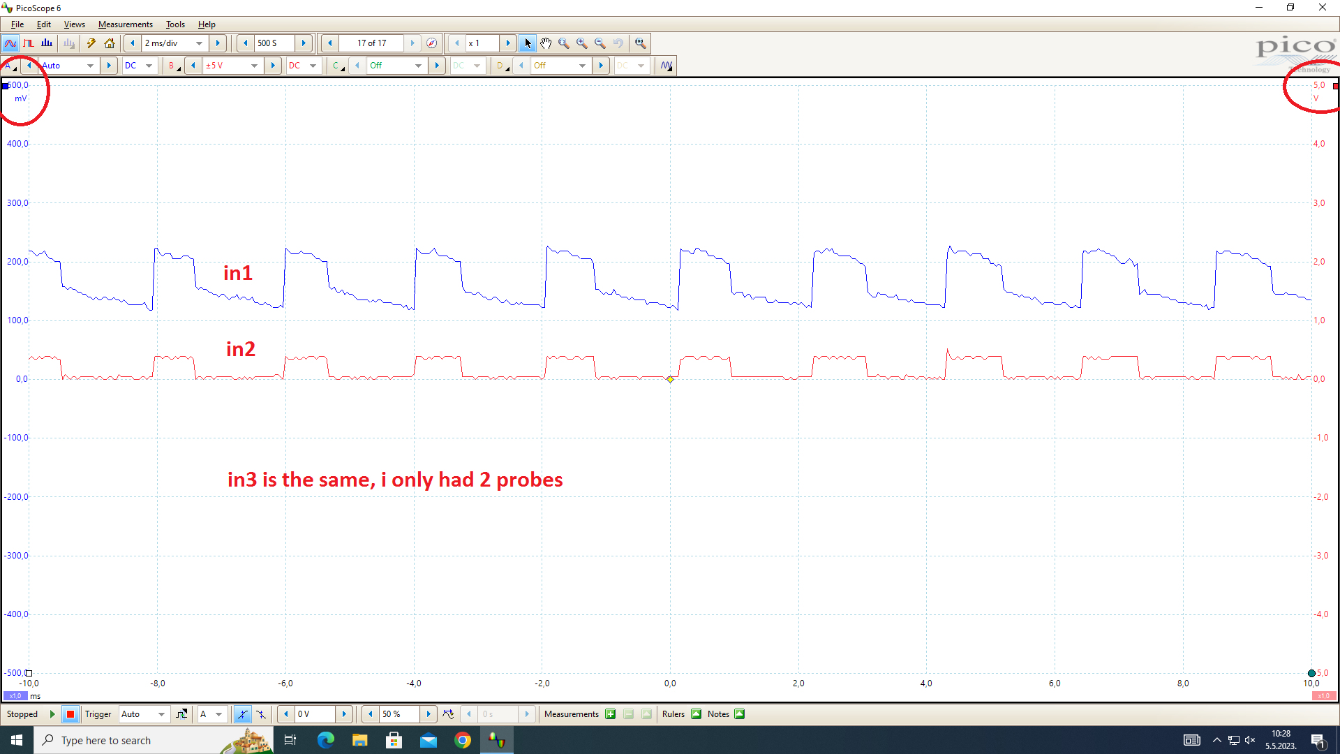
Recorded the PWM pins, this doesnt seem right but idk enough about FOC to dispute it…
target_velocity was set to 5
200mV seems veeery low, my prof thought it was noise before I checked and it wasnt on any of the other pins. the 3 pins have the same waveform pwmA(in1) pwmB(in2) pwmC(in3).
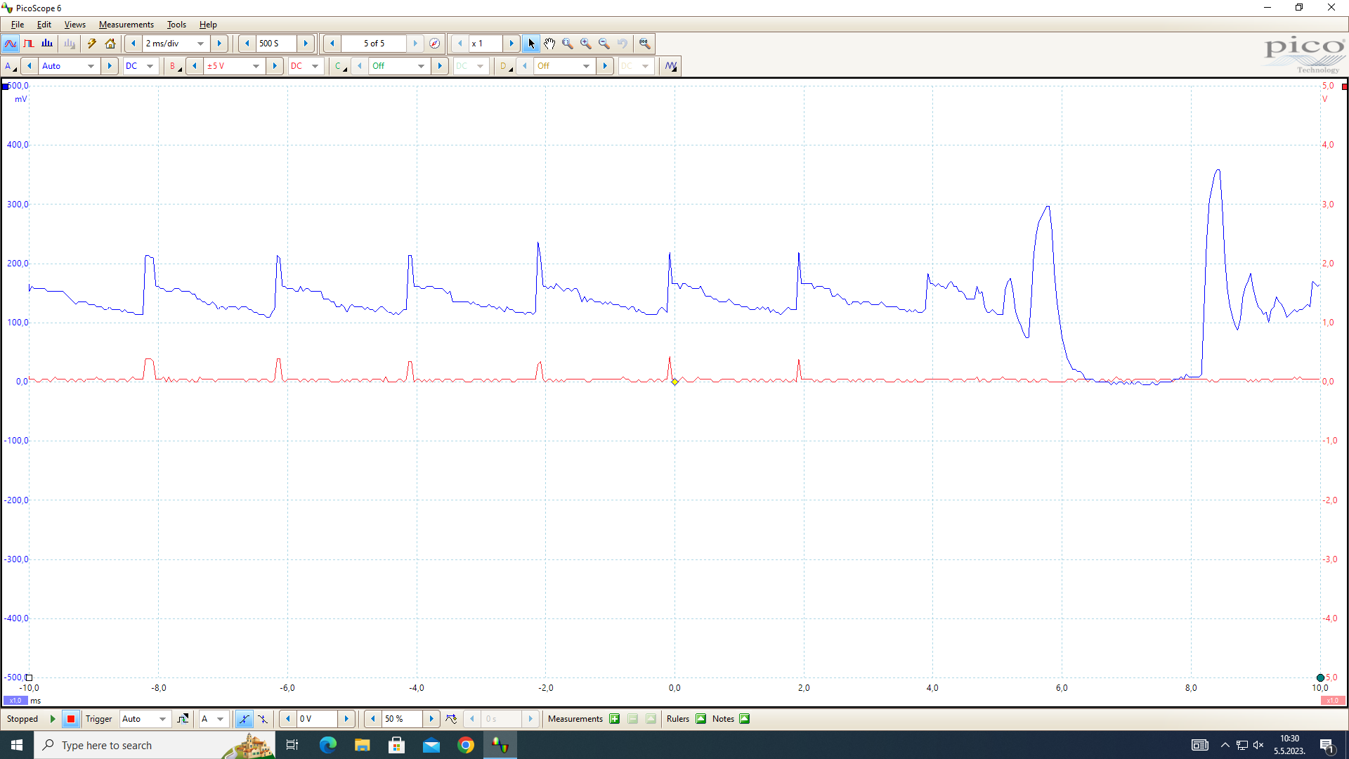
Then theres this weird waveform that appears periodically every few secs:
In case there was smth wrong w my Nucleo I loaded the code onto another one I borrowed from a friend and it was the same.
Could you change these : PA_8, PA_9, PA_10, PA_5
to this: PA8, PA9, PA10, PA5
Does this make any difference?
It. uh. works. That fixed it, everything.
you cant see me, but my face is a rictus of anguish. im being funny but its true
![]()
Its not like I’ve not been bitten by this before, esp in combination with auto-complete its easy to make this mistake.
Lets agree that its a bug in the STM32 Arduino framework to define these constants in this confusing way ![]()
Some examples would help in the commander docs, I forget now how to do it but I remember it did take me a while to figure it out. It’s a good design, the documentation is just lacking examples to really glue things together and mop up those last few uncertainties on exactly what command looks like. That actual character that is used to refer to the usual first motor is A or something, it took me a while to ascertain that.