Open loop velocity control not working at low velocity

Hi my BLDC motor doesn’t rotate at low velocity (1 rad/s), but it can rotate at high velocity like 10 rad/s. Since it was rotating smoothly at 1 rad/s until yesterday with the following code, I’m wondering why this doesn’t work now:

#include <SimpleFOC.h>

BLDCMotor motor = BLDCMotor(11);
BLDCDriver3PWM driver = BLDCDriver3PWM(6, 9, 10, 11);

float target_velocity = 0;

Commander command = Commander(Serial);
void doTarget(char* cmd) { command.scalar(&target_velocity, cmd); }
void doLimit(char* cmd) { command.scalar(&motor.voltage_limit, cmd); }

void setup() {
  driver.voltage_power_supply = 12;
  driver.voltage_limit = 6;
  driver.init();
  motor.linkDriver(&driver);

  motor.voltage_limit = 3;
  motor.controller = MotionControlType::velocity_openloop;

  motor.init();

  command.add('T', doTarget, "target velocity");
  command.add('L', doLimit, "voltage limit");

  Serial.begin(115200);
  Serial.println("Motor ready!");
  Serial.println("Set target velocity [rad/s]");
  _delay(1000);
}

void loop() {
  motor.move(target_velocity);
  command.run();
}

This code is from open loop velocity control example. It was running smoothly before with this code.
MCU: arduino nano
BLDC motor: GBM5208-75T 24n22p 15.0Ω
FOC board: SimpleFOCMini
Supply voltage: 12v

Things I tried:

  • use a new motor
    → still the same
  • check soldering
    → looked okay
  • use a different MCU
    → tried with STMF103CBT6, but the same result
  • increase the voltage
    → I changed voltage_limit to 5v, but it doesn’t rotate at 1 rad/s either
  • decrease the voltage
    → I changed voltage_limit to 2v, then it started rotating with 3 rad/s, but it doesn’t work with 1 rad/s.
  • driver_standalone_test
    → worked

When I set 1 rad/s, the current draw is fluctuating around 52~92mA and the motor just move back and forth. While I set 10 rad/s, the current draw is around 40mA.

I would really appreciate if you guide me how to debug this. I have a logic analyzer, but not a oscilloscope.
Btw this project is super awesome. Thank you for everything you guys have done.

What if you set driver.voltage_limit = 12 or you don’t set it? (driver.voltage_limit will be equal to driver.voltage_power_supply)

Thanks for the quick response! I just tried that and the motor still move back and forth at 1 rad/s.

Could it be there is no signal/voltage on one of the phases ?
You could measure that with a voltmeter.

Okay, I measured each pin’s output with a multimeter and all of them outputs similar voltage range: 4~8v while the motor attempts to rotate at 1 rad/s.

This error is very hard to understand from your description. I agree with Candas from the way it sounds a likely cause would be one of the phases not working/not well connected.
Otherwise, for open loop mode, your code looks fine and there is no reason it should not work at 1rad/s if it is working at 10rad/s. In open loop mode the amplitude of these commutation signals should be the same (motor.voltage_limit) and the only difference should be the frequency.

When the motor is unpowered, and you turn it by hand, is it easy to turn or is there some kind of friction or asymmetry in the motor that makes it “stick”?

Okay, thank you for your response! I will share the videos of running at 1 rad/s and 10 rad/s since I can upload file now.


1 rad/s


10 rad/s

Yes, I can easily turn by hand. It seems fine except I feel some cogging which I think it’s normal. If one of the phases not working/not well connected, should I open up the motor and check the soldering?

You’re right. I checked the continuity of each phases and figured phase C is not connected to the other. Both motors have the same issue. I’m going to fix that. Thank you for looking into this!

1 Like

Hi,

I am very new to SimpleFOC, and I have a very similar challenge I hope I can get help with.

I fried a couple of MKS DUAL FOC V3.2
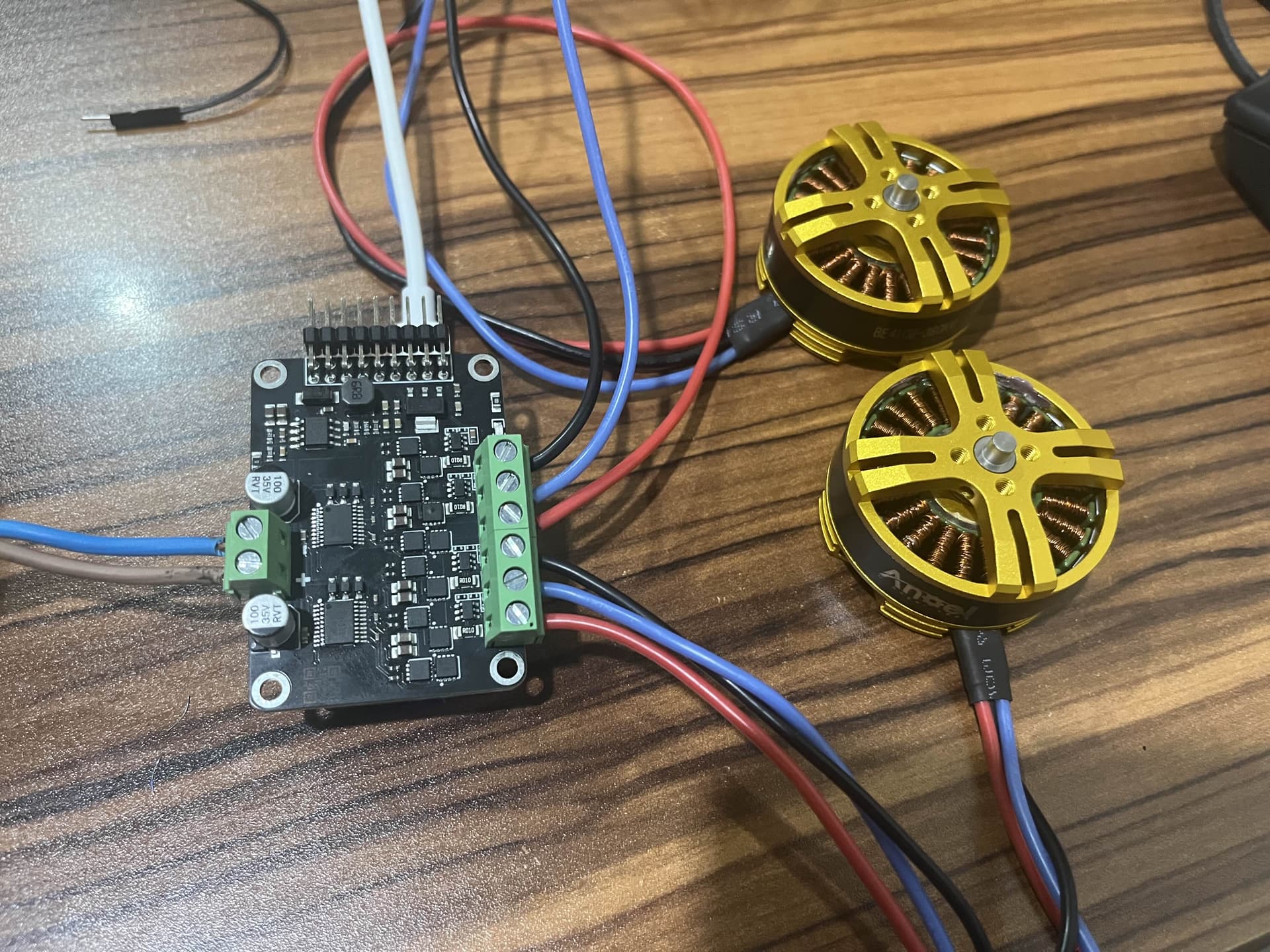
driver boards. (Mks dual foc v3.1? - #18 by IB_Mr.0_o) and I replaced them with a couple of V3.3 Plus:

I haven’t managed to fry one yet (touch wood), but I cannot get it to work properly.

I have two motors I am trying to get going:

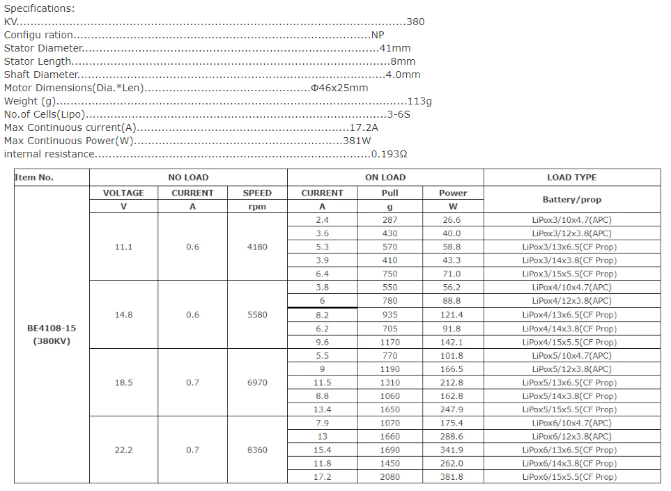
I have the 380KV model and an iPower gimbal motor:

Some of the specifications

  • Model: GM6208
  • Configuration: 24N/28P
  • No-load current: 0.08±0.1 A
  • No-load volts: 20 V
  • No-load Rpm: 209~231 RPM
  • Load current: 1.2 A
  • Load volts: 20 V
  • Load torque(g·cm): 2600-3600
  • Motor internal resistance: 32Ω±5%(Resistance varies with temperature)
  • High voltage test: DC500V 1mA @2sec
  • Maximum power: ≤25W
  • Working current: 3-5S

I am really struggling to understand how to extract the right values to use with them. I have installed simpleFOCstudio in the hopes it would help me do so, but haven’t managed to connect a motor to it yet as I can’t get the code from this page to compile: SimpleFOCStudio | Arduino-FOC

I have taken their open loop velocity example: MKS-DUALFOC/Test Code/1_open_loop_velocity_example at main · makerbase-motor/MKS-DUALFOC · GitHub and made my best guesses.

/// MKS ESP32 FOC Open loop speed control example; Test Library:SimpleFOC 2.1.1 ; Tested hardware:MKS ESP32 FOC V1.0
/// Enter "T+number" in the serial port to set the speed of the two motors.For example, to set the motor to rotate at a speed of 10rad/s, input "T10"
/// When the motor is powered on, it will rotate at 5rad/s by default
/// When using your own motor, do remember to modify the default number of pole pairs, the value in BLDCMotor(7).
/// The default power supply voltage of the program is 12V.
/// Please remember to modify the voltage_power_supply , voltage_limit variable values when using other voltages for power supply

#include <SimpleFOC.h>

BLDCMotor motor = BLDCMotor(6);                               //According to the selected motor, modify the number of pole pairs here, the value in BLDCMotor()
BLDCDriver3PWM driver = BLDCDriver3PWM(32,33,25,22);
  
/// BLDC motor & driver instance
BLDCMotor motor1 = BLDCMotor(8);                              //Also modify the value in BLDCMotor() here
BLDCDriver3PWM driver1  = BLDCDriver3PWM(26,27,14,12);

/// Target Variable
float target_velocity = 5;

/// Serial Command Setting
Commander command = Commander(Serial);
void doTarget(char* cmd) { command.scalar(&target_velocity, cmd); }

void setup() {
  

  driver.voltage_power_supply = 12;                   //According to the supply voltage, modify the value of voltage_power_supply here
  driver.init();
  motor.linkDriver(&driver);
  motor.voltage_limit = 3;   // [V]                   //According to the supply voltage, modify the value of voltage_limit here
  motor.velocity_limit = 40; // [rad/s]
  
  driver1.voltage_power_supply = 12;                  //Also modify the value of voltage_power_supply here
  driver1.init();
  motor1.linkDriver(&driver1);
  motor1.voltage_limit = 3;   // [V]                  //Also modify the value of voltage_limit here
  motor1.velocity_limit = 40; // [rad/s]

 
  // Open Loop Control Mode Setting
  motor.controller = MotionControlType::velocity_openloop;
  motor1.controller = MotionControlType::velocity_openloop;

  // Initialize the Hardware
  motor.init();
  motor1.init();


  // Add T Command
  // Enter "T+number" in the serial port to set the speed of the two motors.For example, to set the motor to rotate at a speed of 10rad/s, input "T10".
  command.add('T', doTarget, "target velocity");

  Serial.begin(115200);
  Serial.println("Motor ready!");
  Serial.println("Set target velocity [rad/s]");
  //_delay(1000);
}

void loop() {
  motor.move(target_velocity);                    //When the motor is powered on, it will rotate at 5rad/s by default
  motor1.move(target_velocity);

  //User Newsletter
  command.run();
}

Like @hkyuchiaoki hkyuchiaoki I am seeing eratic low speed behaviour and mo movement at >10 rads/sec: files at theIdeaClub

I have checked the continuity and they all look good. They are drawing almost 2A!

As I said this is all new to me and I am at a loss.

How does one determine the number of pole pairs? I assumed being 3 phase it is simply 1/3 the number of stators. Or being pole pairs would it be 1/6? It doesn’t seem to matter what value I put in there the behaviour is similar.

Please and thanks for any suggestions on what I am doing wrong!

The Sunnysky has 170 milliohm resistance, so with your motor.voltage_limit=3 that’s 3/0.17=17.6A at the motor, which should be 4.4A at the power supply where voltage is 12V. Not sure why you’re only seeing 2A, but use lower voltage limit (1V or less) or it will probably burn.

The 32 ohm gimbal motor should be 3/32=0.094A, so practically nothing at the power supply. It may need higher voltage to turn. Try motor.voltage_limit=6 (which is the highest you can go with 12V supply and SinePWM modulation https://docs.simplefoc.com/foc_theory)

Half the number of rotor magnets. Sunnysky says 24 rotor poles, so 12 pairs for it. Gimbal says 24N/28P so 14 pairs for it (N is nuten, the German word for stator slots, P is rotor magnet poles).

2 Likes

What a wonderful day for me. :slightly_smiling_face:

Between that and:

The gimbal motor is turning beautifully and drawing only 40 ma.

Interestingly however, only up to 10 RADS/sec:

Sorry about the shaky video (I guess I need a tripod.) The last 3 speeds are 10 RADS/sec, then 11, then back to 10.

What might cause that?

Is this because of the legacy of hobbyists rewinding CDROM motors “back in the day”? Where would we be without German ingenuity!

The Sunnysky is still not right. Family duties today - but I am so excited with this you can be sure “I shall return”.

I cannot tell you how much I appreciate this.

warm regards

1 Like

Glad I could help!

Either the instantaneous change in stator field speed is getting ahead of the rotor due to its inertia and then failing to get back in sync, or you’ve hit the limit of what it can do with a 12V power supply. The specs in your previous post say ~220RPM at 20V, so 12V should be ~14rad/s. Perhaps 16 if you use SpaceVectorPWM which will allow motor.voltage_limit up to 7V.

In any case, open loop mode is really only good for testing to see if the hardware works at all. For reliable spinning and good torque, you’ll either need a position sensor, or once you get the current sense configured you can use the sensorless flux observer for velocity mode. It’s tedious to tune the parameters for it, but once you do it works well. But if your final goal is angle control, then you’ll definitely need a position sensor.

Try running the gimbal on the other side of the driver to make sure the Sunnysky hasn’t already burnt a mosfet. Sometimes they go out in a blaze of sparks and burnt fiberglass smell, but 17A is low enough that it would probably be ok for a while and then die quietly.

Makes sense. I’ll push it to 20v. 220 RPM is sufficient for the proof of concept I am working on.

I am indeed planning on doing closed loop. I have some of these:

and am waiting for these:

Once I get my documentation done, I’ll post the project in another thread.

Thanks again. This has put an extra shine on my day.

So my I clearly limited understanding of phase resistance is still a challenge.

I measured the resistance between the phases of a couple of these: NEEBRC 3542 920KV Outrunner Brushless Motor with Hobbywing 50A V2 ESC for RC FPV Fixed Wing Glide Drone Aircraft Warbirds

And got similar values on my multi-meter as I do on the Sunnysky. I clearly need a better meter for this as 200 ohms is the lowest setting it has.

Thinking I had learned from your post @dekutree64 I set what I thought were conservative values, limiting motor voltage to 0.25v.

On applying power the little MKS DUAL FOC V3.3 instantly flared like a match. I think I am getting addicted to that smell… :wink:

I could not find any data on the real phase/motor resistance nor get confirmation of the number of poles. I have not yet disassembled one to look but am tempted to. It clearly has 12 stators and I am assuming 14 poles as that seems to be a common configuration on these types of motors.

These motors each come with 50A ESCs and I suspect they simply need more power than what this hardware can deliver.

Should I expect to be able to drive these at all with this little driver board with appropriate settings or am I literally expecting it to work beyond what it is designed to do?

It should be ok. You won’t be able to use the full power of that Hobbywing, but the board certainly shouldn’t explode on contact. I would guesstimate its resistance around 50mOhm, so 0.25v would be around 5A, which should be fine. And yes that motor surely has 14 magnets (7 pole pairs).

Instant explosion is probably some configuration error. Can you see what burned? Any chance you had the power wires polarity reversed?

EDIT: Checked on ebay and found a C3542 motor with more specs and it looks like the resistance is more like 25mOhm, so 10A. That will probably get hot, but still shouldn’t explode instantly.

thanks @dekutree64

I will try this again using my power supply. The application requires I use batteries. I used a 40C 4S LiPo which seems to be a common factor with my exploding driver boards. I am pretty confident I had the polarity right.

I have fried 4 boards now, 3 spectacularly with light shows, but have 4 more and even though thanks to you and @motormaker I have changed my approach to use ESCs with the motors, I am stubborn and want to understand/succeed in this so I will post all my settings here again before hooking up the power supply.

What are your thoughts on the LiPo Vs the power supply being related? The PS is set to constant voltage mode and I am unsure if it limits the current. I see no options to set a limit.

In the subject of LiPos. The GM6208-150T Gimbal Motor is rated to 20V. a 4S is only 14.8V but a 6S 22.2V Given the low current draw on this, do you think it risky to use a 6S 22.2V on this motor?

1 Like

Not risky at all. For the most part, motors have no voltage limit, and the ratings are just recommendations for good performance. You have to exceed the winding insulation strength (hundreds of volts) or spin it fast enough for mechanical failure (difficult to achieve on a high resistance gimbal motor). Usually it’s the mosfets and capacitors that limit the voltage of a system.

Lipo versus power supply shouldn’t matter.

1 Like