Thanks for that, with your suggestion I have determined (I think) which pins on the DualFOC header pins go to which pins on the ESP32.
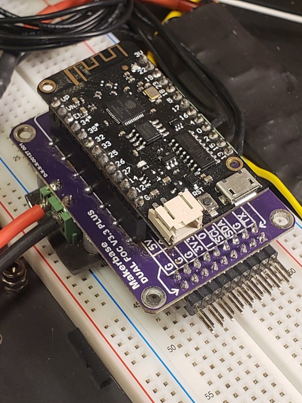
I wired up a harness for it:
And it gets plugged in here:
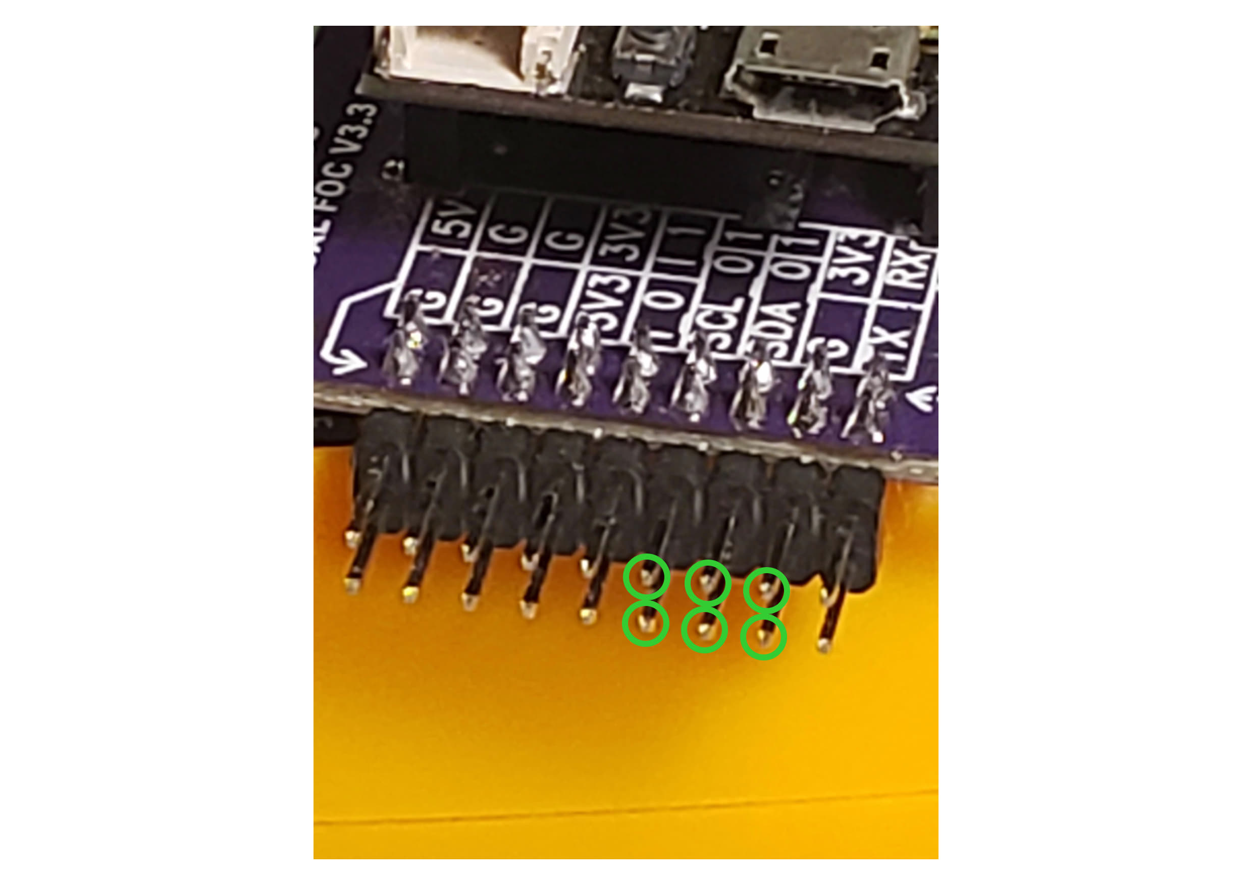
I have continuity between the soldered pads on the AS5048A and the GPIO pins on the ESP32 for all 6 lines using this as a reference: ESP32 Pinout Reference - Last Minute Engineers
According to this: Magnetic sensor SPI | Arduino-FOC I believe I should:
- create an instance of the
MagneticSensorSPI class. I used GPIO5 for chip_select, I can confirm continuity between the AS5048A nCS solder pad and GPIO5 on the ESP32:
MagneticSensorSPI sensor = MagneticSensorSPI(5, 14, 0x3FFF);
- Initialize and link the sensor:
// init magnetic sensor hardware
  sensor.init();
  motor.linkSensor(&sensor);
- Initialize and link the driver:
// driver
  driver.init()
  motor.linkDriver(&driver);
- Initialize the motor:
// init motor hardware
  motor.init();
  motor.initFOC();
- call loopFOC() and move() in the main loop:
void loop(){
  motor.loopFOC();
  motor.move();
So I loaded the closed loop example full_control_serial from the Arduino examples, modified for my motor and sensor:
/**
 * Comprehensive BLDC motor control example using magnetic sensor
 *
 * Using serial terminal user can send motor commands and configure the motor and FOC in real-time:
 * - configure PID controller constants
 * - change motion control loops
 * - monitor motor variabels
 * - set target values
 * - check all the configuration values
 *
 * See more info in docs.simplefoc.com/commander_interface
 */
#include <SimpleFOC.h>

// magnetic sensor instance - SPI
MagneticSensorSPI sensor = MagneticSensorSPI(5, 14, 0x3FFF);

// BLDC motor & driver instance
BLDCMotor motor = BLDCMotor(14);
BLDCDriver3PWM driver = BLDCDriver3PWM(32,33,25,22);

// commander interface
Commander command = Commander(Serial);
void onMotor(char* cmd){ command.motor(&motor, cmd); }

void setup() {

  // use monitoring with serial
  Serial.begin(115200);
  // enable more verbose output for debugging
  // comment out if not needed
  SimpleFOCDebug::enable(&Serial);

  // initialise magnetic sensor hardware
  sensor.init();
  // link the motor to the sensor
  motor.linkSensor(&sensor);

  // driver config
  // power supply voltage [V]
  driver.voltage_power_supply = 12;
  driver.init();
  // link driver
  motor.linkDriver(&driver);

  // choose FOC modulation
  motor.foc_modulation = FOCModulationType::SpaceVectorPWM;

  // set control loop type to be used
  motor.controller = MotionControlType::torque;

  // contoller configuration based on the control type
  motor.PID_velocity.P = 0.2f;
  motor.PID_velocity.I = 20;
  motor.PID_velocity.D = 0;
  // default voltage_power_supply
  motor.voltage_limit = 12;

  // velocity low pass filtering time constant
  motor.LPF_velocity.Tf = 0.01f;

  // angle loop controller
  motor.P_angle.P = 20;
  // angle loop velocity limit
  motor.velocity_limit = 50;

  // comment out if not needed
  motor.useMonitoring(Serial);

  // initialise motor
  motor.init();
  // align encoder and start FOC
  motor.initFOC();

  // set the inital target value
  motor.target = 2;

  // define the motor id
  command.add('A', onMotor, "motor");

  // Run user commands to configure and the motor (find the full command list in docs.simplefoc.com)
  Serial.println(F("Motor commands sketch | Initial motion control > torque/voltage : target 2V."));

  _delay(1000);
}


void loop() {
  // iterative setting FOC phase voltage
  motor.loopFOC();

  // iterative function setting the outter loop target
  // velocity, position or voltage
  // if tatget not set in parameter uses motor.target variable
  motor.move();

  // user communication
  command.run();
}
The driver board has a 5V out which I pass to the ESP32 so it is powered when no serial cable is connected to the PC:
If I leave the power connection from the Driver board to the ESP32 I am getting this in the serial monitor on a reset:
rst:0x1 (POWERON_RESET),boot:0x1b (SPI_FAST_FLASH_BOOT)
configsip: 0, SPIWP:0xee
clk_drv:0x00,q_drv:0x00,d_drv:0x00,cs0_drv:0x00,hd_drv:0x00,wp_drv:0x00
mode:DIO, clock div:1
load:0x3fff0030,len:4916
load:0x40078000,len:16436
load:0x40080400,len:4
ho 8 tail 4 room 4
load:0x40080404,len:3524
entry 0x400805b8
ESP32-DRV: Configuring 3PWM in group: 0 on timer: 0
ESP32-DRV: Configuring 2 operators.
ESP32-DRV: Configuring 3 comparators.
ESP32-DRV: Configuring 3 generators.
ESP32-DRV: Configuring center-aligned pwm.
ESP32-DRV: Enabling timer: 0
ESP32-DRV: MCPWM configured!
MOT: Monitor enabled!
MOT: Init
MOT: Enable driver.
MOT: Align sensor.
MOT: Failed to notice movement
MOT: Init FOC failed.
Motor commands sketch | Initial motion control > torque/voltage : target 20V.
If I disconnect the power leaving only the USB serial 5V I get this on reset:
rst:0x1 (POWERON_RESET),boot:0x1b (SPI_FAST_FLASH_BOOT)
configsip: 0, SPIWP:0xee
clk_drv:0x00,q_drv:0x00,d_drv:0x00,cs0_drv:0x00,hd_drv:0x00,wp_drv:0x00
mode:DIO, clock div:1
load:0x3fff0030,len:4916
load:0x40078000,len:16436
load:0x40080400,len:4
ho 8 tail 4 room 4
load:0x40080404,len:3524
entry 0x400805b8
ESP32-DRV: Configuring 3PWM in group: 0 on timer: 0
ESP32-DRV: Configuring 2 operators.
ESP32-DRV: Configuring 3 comparators.
ESP32-DRV: Configuring 3 generators.
ESP32-DRV: Configuring center-aligned pwm.
ESP32-DRV: Enabling timer: 0
ESP32-DRV: MCPWM configured!
MOT: Monitor enabled!
MOT: Init
MOT: Enable driver.
MOT: Align sensor.
MOT: sensor_direction==CW
MOT: PP check: fail - estimated pp: 0.97
MOT: Zero elec. angle: 1.18
MOT: No current sense.
MOT: Ready.
Motor commands sketch | Initial motion control > torque/voltage : target 20V.
What is:
MOT: PP check: fail - estimated pp: 0.97
MOT: Zero elec. angle: 1.18
I had expected after this to be able to enter commander commands at the serial console and be able to control the motor but I cannot.
I appear to be flailing…
Any suggestions? I am really struggling to get this motor to run in a closed loop.