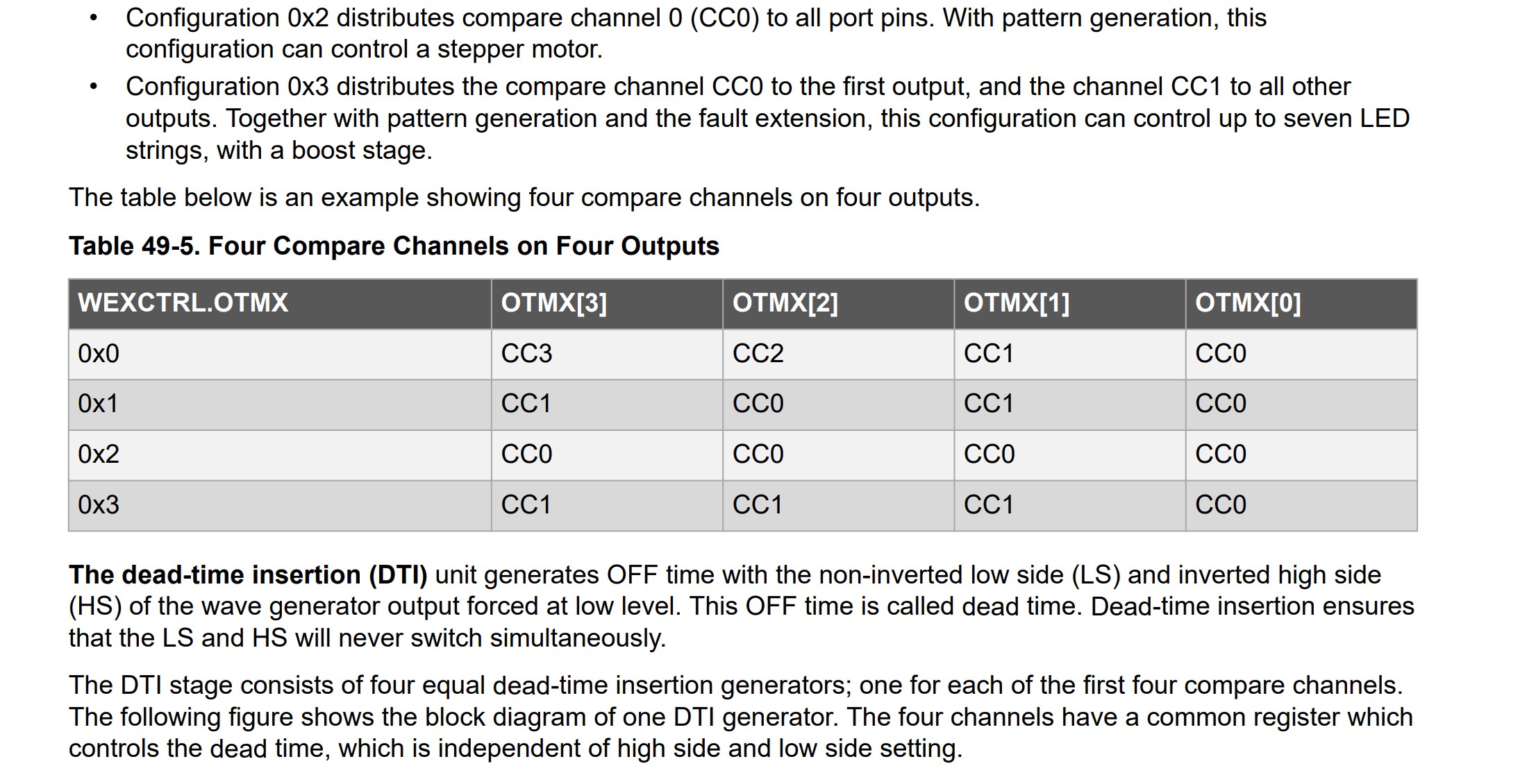
From the table below, I would place the two pins controlling phase 1 on WO-0 and WO-2 , phase 2 = WO-1 and W0-3. And then use 0x1 setting? {CC1 ,CC0, CC1, CC0}. So the two pins controlling the same phase are on the same CC (Compare channel)?
Configuration 0x1 distributes the channels on output modulo half the number of channels. This assigns twice the number of output locations to the lower channels than the default configuration. This can be used, for example, to control the four transistors of a full bridge using only two compare channels.
Im not sure i get the "can control a stepper motor part, if they are all on the same CC0?
Hello. I used MT6701 in abz mode and analog signal.
The bldc motor is specified in the calibration example. I changed it to stepper, but after calibration, the motor does not execute simple rotation commands. Different values run endlessly in the port monitor.
In the case of the bldc motor, the string ‘nan’ appeared and the motor executed commands. But this does not happen with a stepper motor.
I think there must be a way to calibrate the sensor itself. But I haven’t found it yet…
I also centered the sensor and magnet with a tool. But we cannot be sure of the exact magnetization of the magnet and the manufacture of the sensor housing. They clearly have a margin of error.
Thank you
You can configure DMA to move the data from the sensors into RAM. It doesn’t really matter if the transfer happen all at once or if data arrives with big pauses between bytes. Usually, to benefit from DMA there must be a substantial amount of data involved. DMA will not help you if you only want to read one or two bytes. But it all depends on the details.
Using DMA we should be able to offload the MCU, so that it can do FOC while fetching data.
In the MT6835 datasheet it writes to choose between single bit read or burst read mode. When in burst read, the DMA could load the entire message and raise a flag when it’s read. That way the MCU knows when there is new position data available.
Comparing the MT6701 to the MT6835, the MT6701 is recommended for 6mm Ø magnet (2mm distance Max.) and the MT6835 for 10mm Ø magnet (3mm distance Max.).
There are different ways to set up dead-time insertion. One configuration is supposed better for stepper control. Which we would have to call to set up that Compare Channel on those pins. Only for stepper 4pwm use?
Our 4-PWM support doesn’t do dead-time insertion… is it actually needed for steppers? I don’t use them really, so I don’t know much about them. My impression was that the 4 PWMs in this case aren’t controlling 2 half-bridges, and also aren’t pair-wise in opposition like in BLDC driving. I think they have a whole motor winding between the two pairs, so there is no shoot-through…
No, there are 4 pins each controlling a half_bridge. So two of them on the same full bridge (One phase). I guess your point being that one would be ground, the other pwm.
Edit: I see one use case. When the full bridge change direction, there could be shoot_through, where the deadtime would make sure that not both are on at the same time?
Maybe having control of the deadtime between phase direction change is a good thing when fine tuning the driver.
yes exactly!! but since the winding is between the two sides, I think its no problem even to PWM both sides… its just like setting 2 different voltage levels to the two sides of the winding…
I don’t know what the use case is exactly, because I don’t understand steppers so well, but electrically it should be fine.
Again, I don’t see that, because really its like a BLDCDriver3PWM… since you’re using a single PWM to control the half-bridge, the driver hardware is handling the dead-time.
If not, then you would need a StepperDriver8PWM… with this you could control the FETs directly independently. Someone was actually asking about this recently on the forum or GitHub, IIRC… but we don’t have such a thing.
It would also be the case if you were trying to use the StepperDriver4PWM to directly control a H-bridge for some purpose. But that’s not what it’s for…
Here I agree with you - as I said I don’t know enough about it, but I assume there are use-cases like with DC motors where you want to control the “decay” or brake the motor… for such cases independent control of the half-bridges could be needed?
But right now I don’t know enough about it, and I’m not able to really test anything as I only have a few steppers. I think for me personally I have to draw the line somewhere… can’t do everything.
So if someone wants to dig into the stepper code, and improve things, then contributions are always super-welcome… but I won’t be attacking it myself for the foreseeable future… too much to do on the BLDC side still
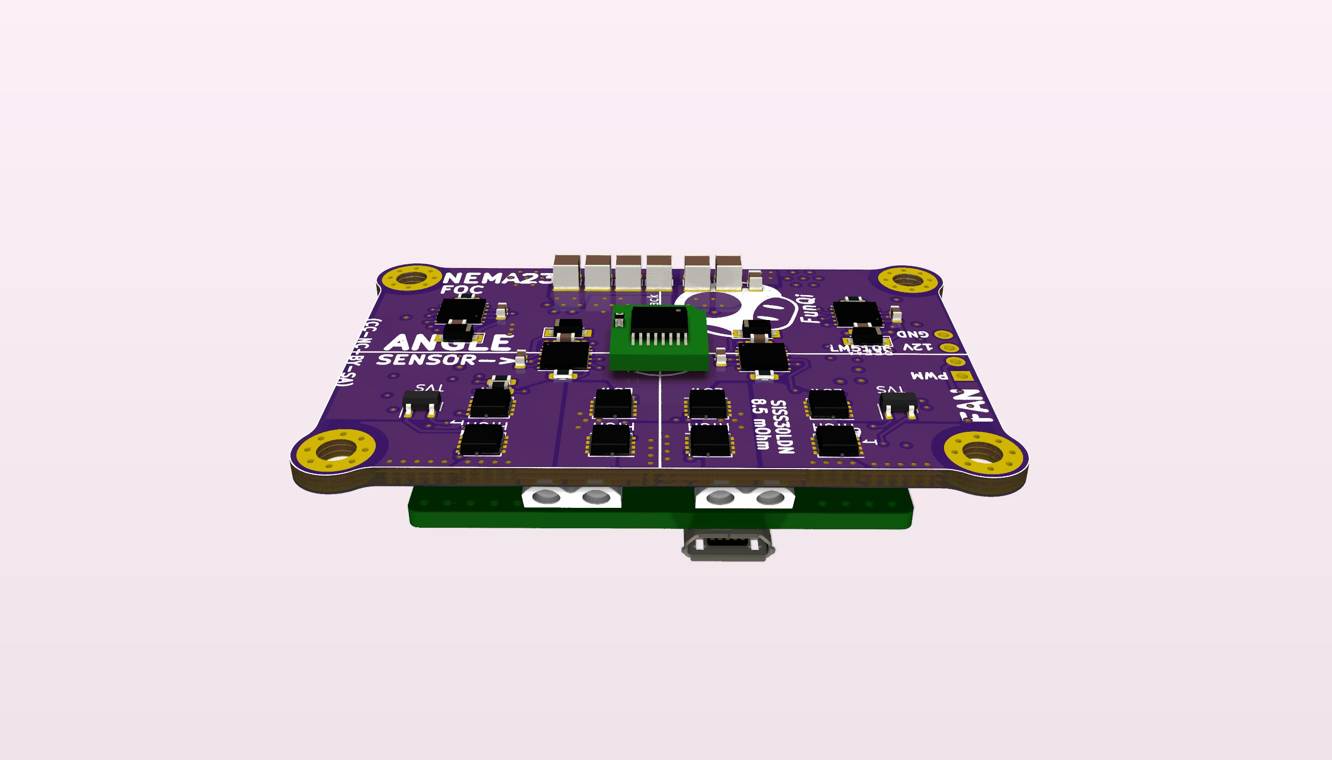
The LM5106 does not have a internal bootstrap dode, like the LM5105. Unfortunately the LM5105 is out of stock. This is a small but important detail. For those who don’t know, the bootstrap diode, makes a path for the bootstrap capacitor to charge, when the LOW side switch is on, making the high side gate driver ready to fire.
This does take out some GND plane area, but we´re still covered pretty good.
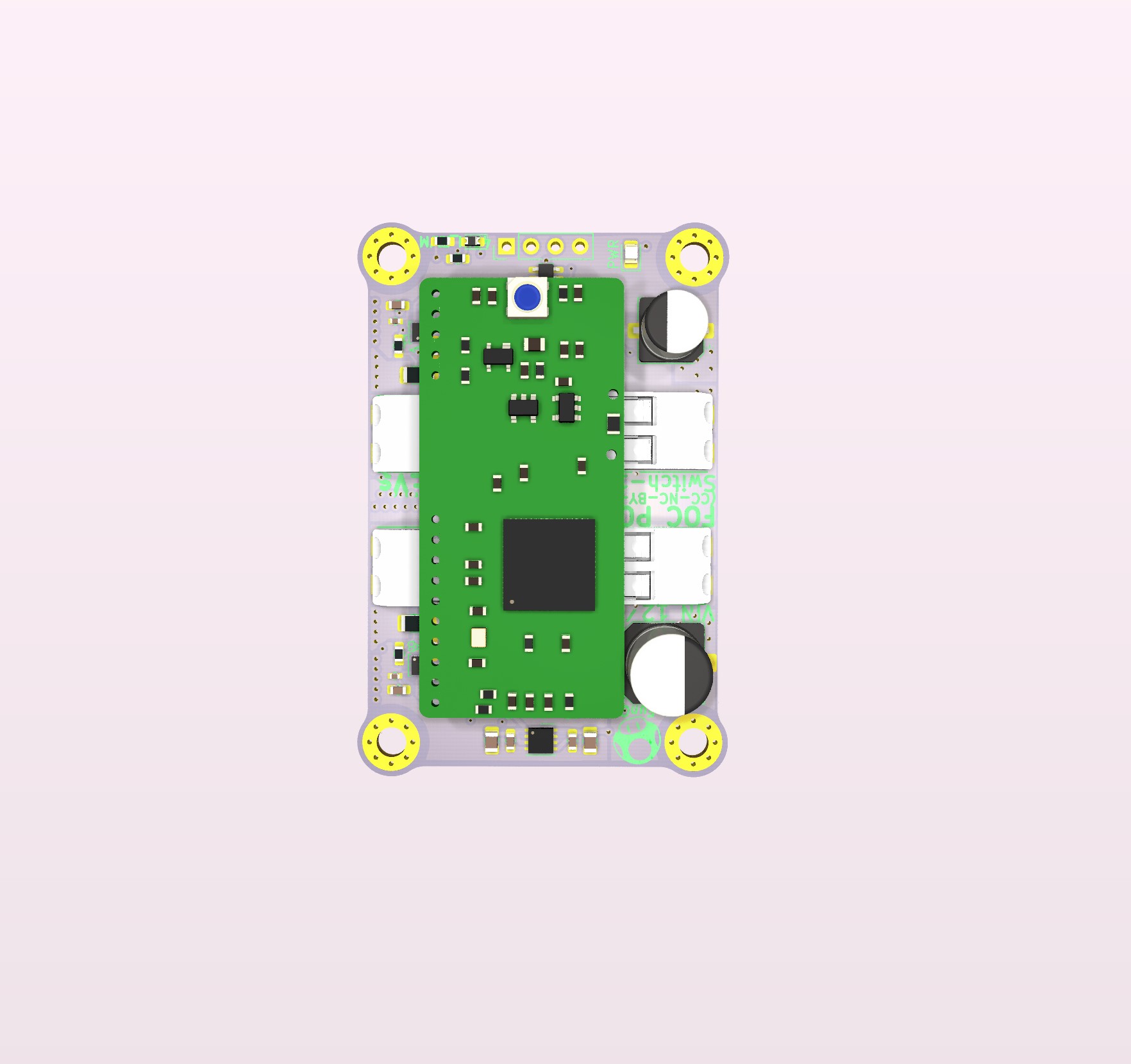
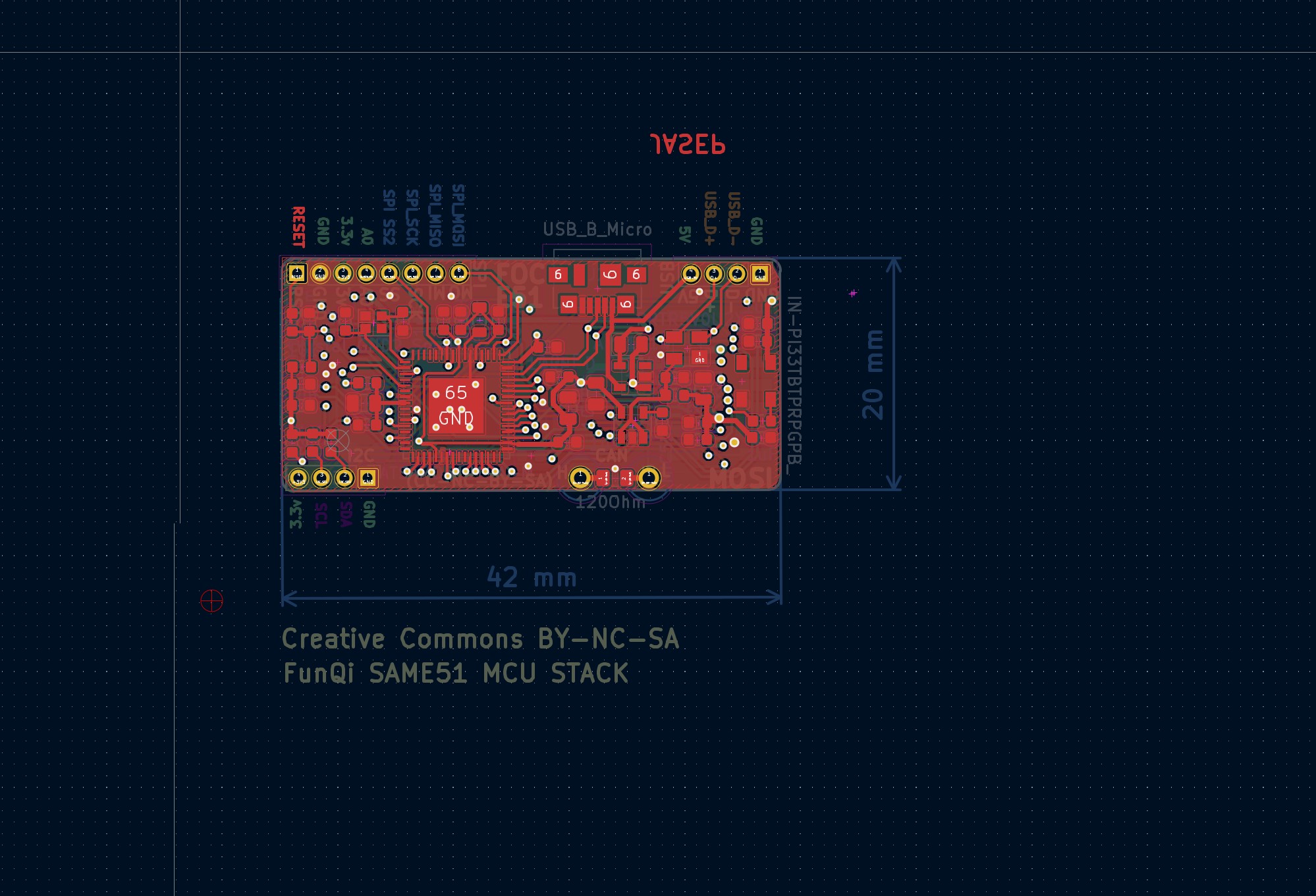
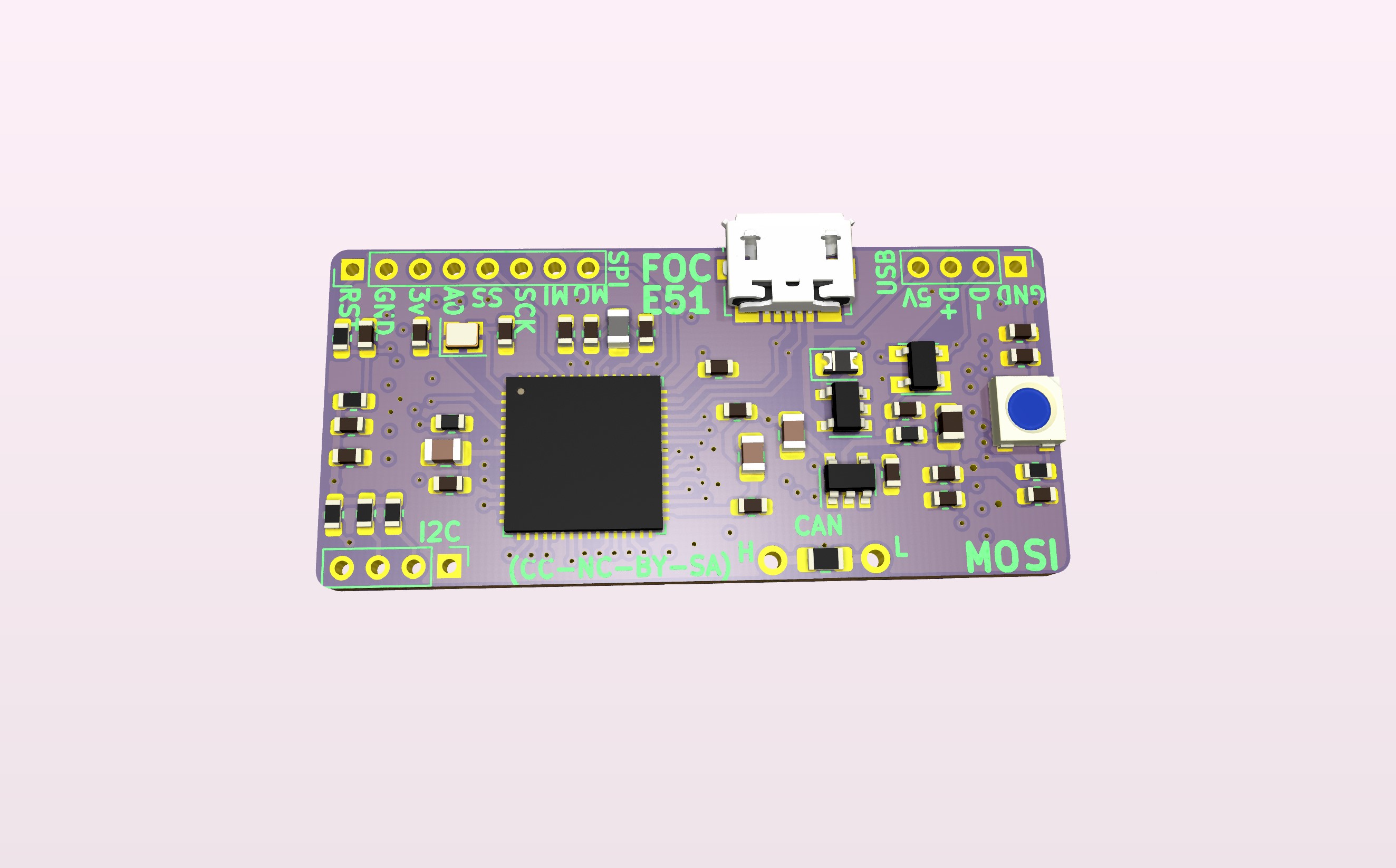
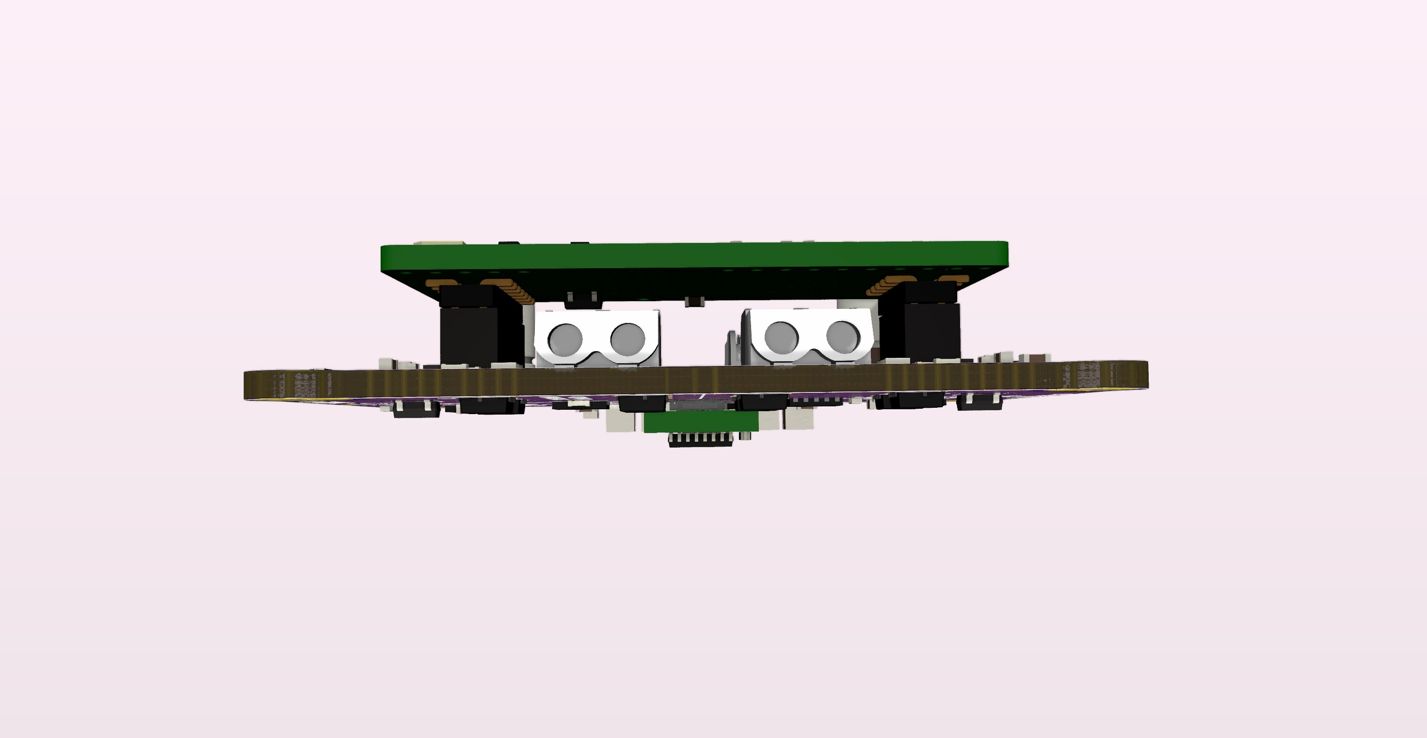
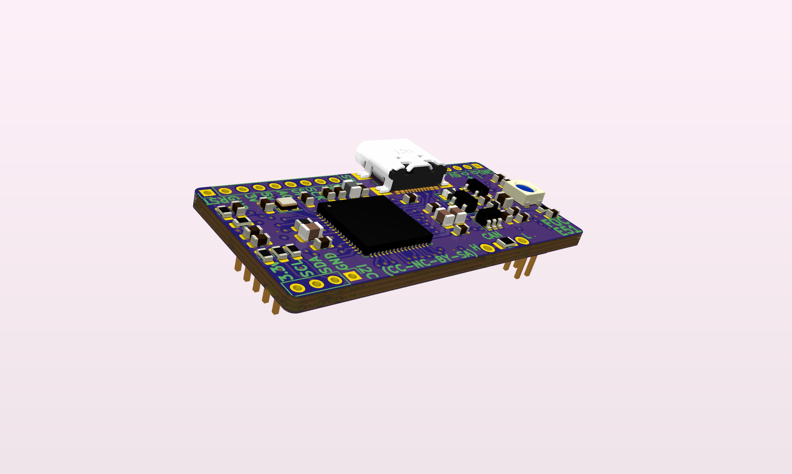
Moving to USB_C plug, since the board is meant for a pretty rough environment, the USB C plug makes a much better link, compared to Micro USB plugs. The price is the same, and you get additional pins. Dont know if there is a MCU USB_C standard for the pins not used by USB 2.0?
Having a 50kHz PWM frequency will make the MOSFET fire 6 times slower than available ADC samples. So 50kHz / 11.667 rps / 200steps = 21,43 PWM cycles per electrical revolution @1400mm/sek.
This means we can oversample to 14bit analog resolution current samples.