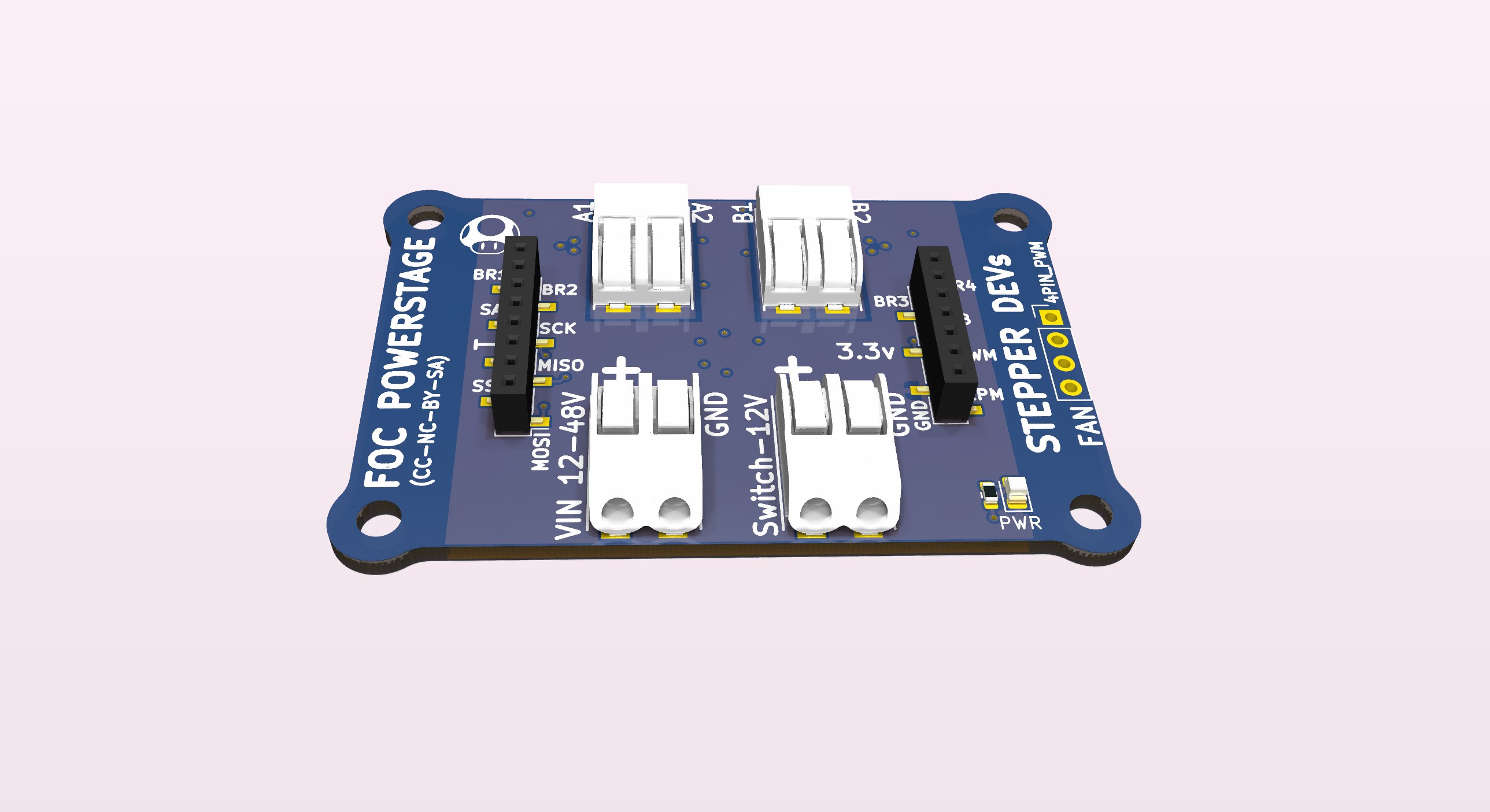
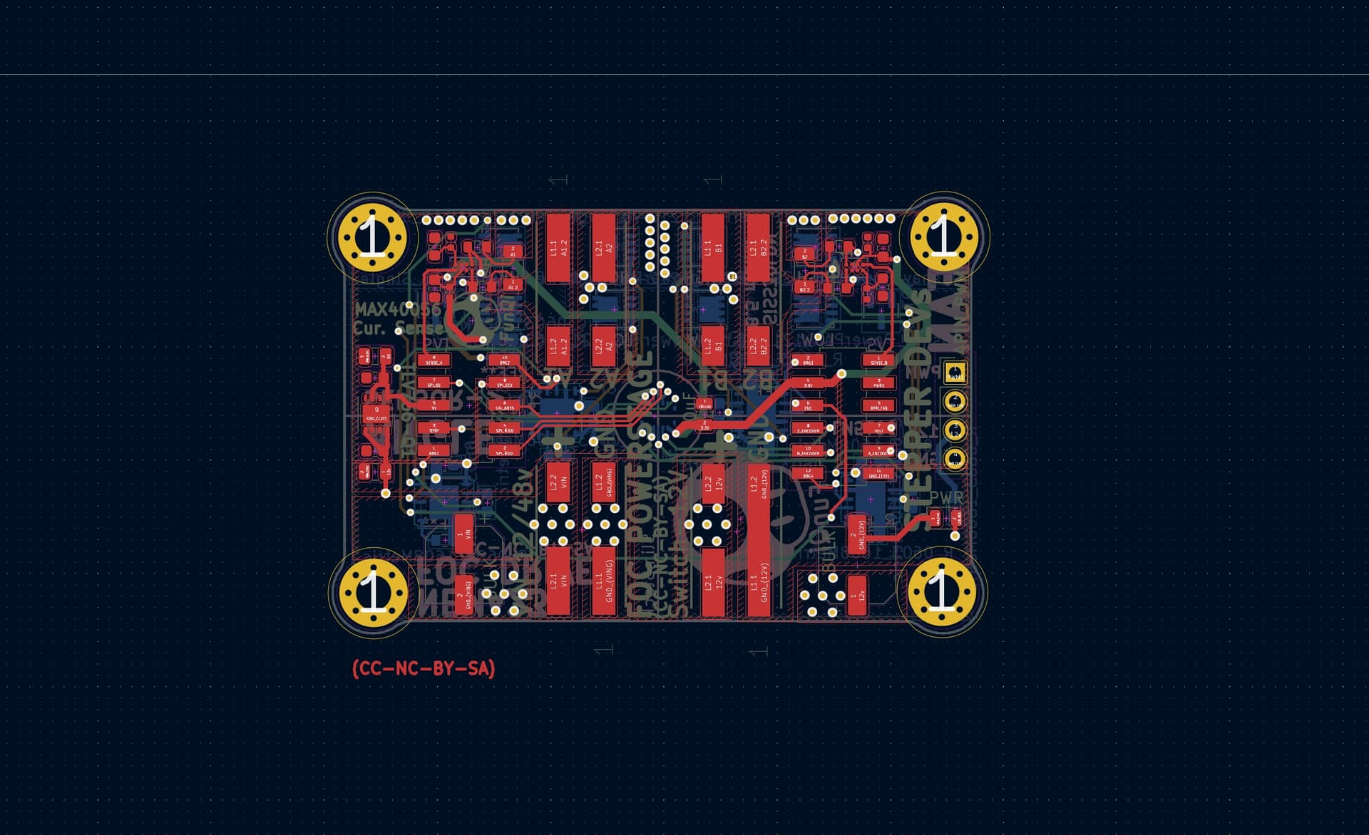
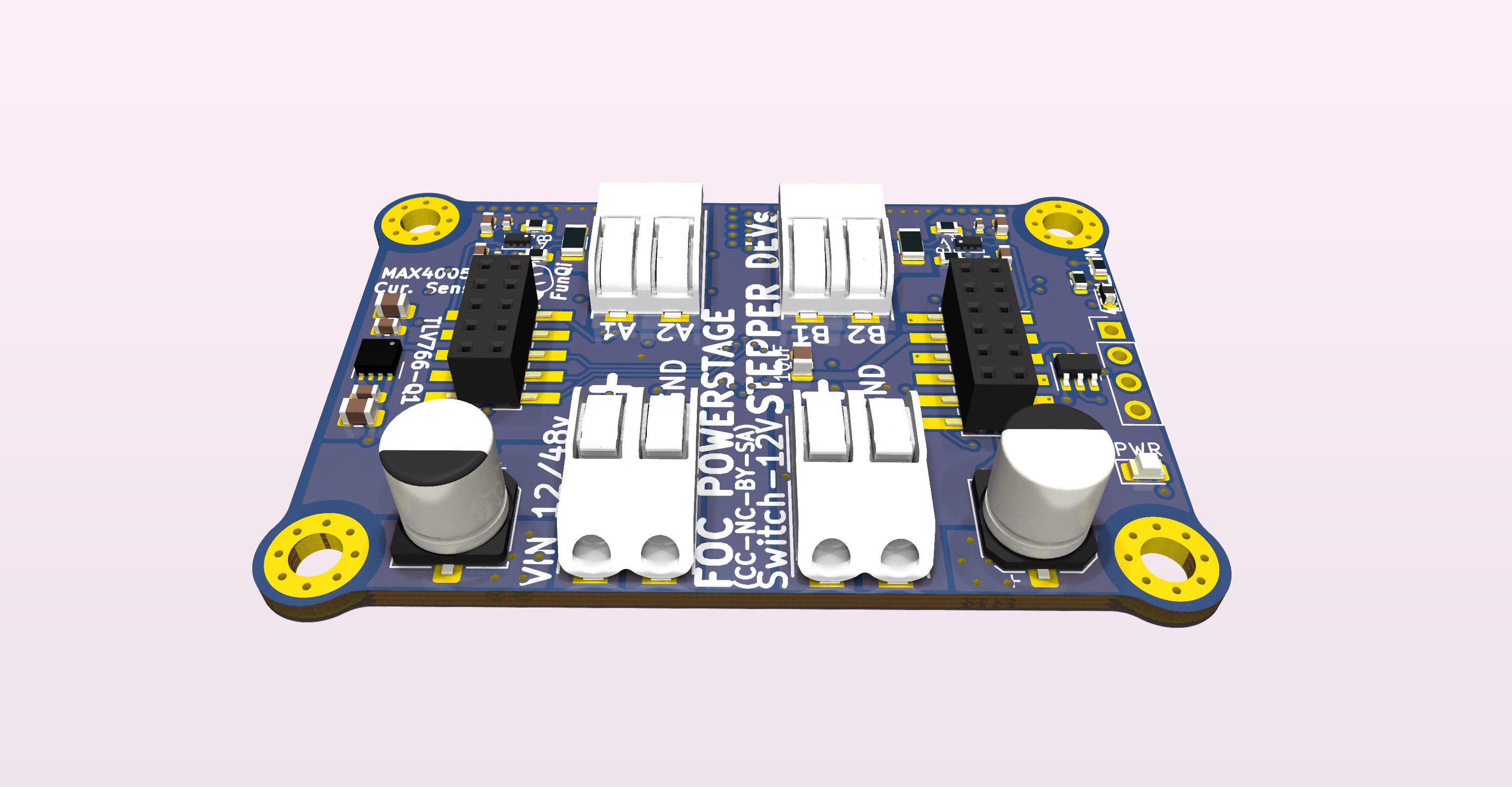
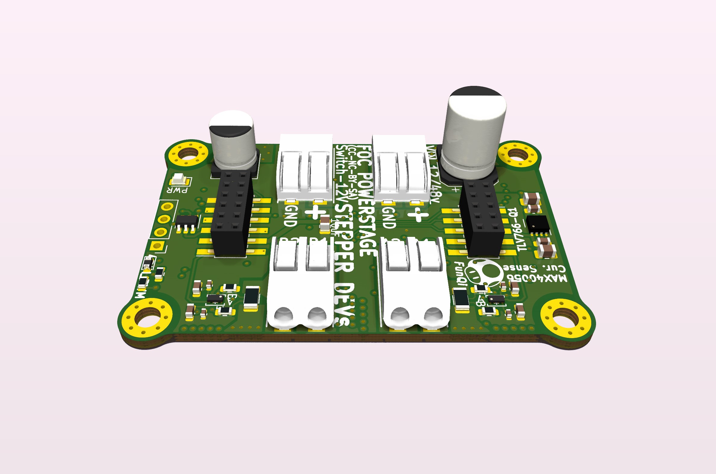
Ive sketched up a possible NEMA23 FOC dev. power stage board (still early design).
It is based on the SiSS30LDN, so it should run very cool if targeting eg. 4 amp NEMA23 steppers.
The thought is, as you can see below, to keep it modular with a separate MCU on top, and also a modular angle sensor on the bottom. This way one can mix and match or do a future upgrade to eg. dual core MCU or something. Hopefully we can get Klipper support up and running, which will tie everything together for a futuristic multiaxial machine with FOC steppers.
Im breaking out the SPI and I2C, possibly with solder pads for QuadSPI, since that Molex SlimStack connector for the angle_sensor has 10 pins.
Impressive looking sensor, but despite its 21bit resolution the accuracy is only ±0.5°… that’s not actually that good.
To get better performance out of it, you have to engage in complicated calibration procedures… to get it to the stated accuracy of an AS5048A or AS5047, you need an external calibration setup with a precision (>21 bit) angle reference…
So I’m not sure how practical this really is. Might be simpler just to use an AS5047…
The accuracy is highly realted to the linearity error, other than the IC itself. Since the magnet and the IC are installed indenpendedly. The installation error will cause an linearity error. But MT6835 has the capability for self calibration for this error. You can find some description in chapter 9 of the datasheet.
The basic calibration should get really good results. I did see it has this quite advanced calibration routine, but first of all we just need to get the basic working.
The reason why I reached out to Magntek, is this thread over @klipper,
What was surprising is that MT6701 is way more precise than any of TLE5012 and AS5047D,
it doesn’t even tremble in 0.01 degree, really smooth (14bits), while TLE5012 trembles around 0.02 deg from time to time on turned off motor.
AS5047D had worst documentation, and it trembles a lot,
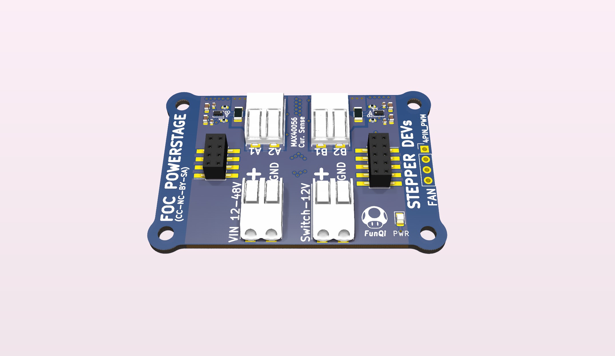
Added MAX40056 bi-directional current sensors with voltage spike protection (48 working-voltage).
Changed headers to double-row for better fit for ABZ interface. The idea is to have SPI and ABZ angle-sensor interface, although only SPI could suffice. The reason for breaking out the ABZ interface is because some MCUs has hardware encoder interface and frankly I don’t know how they compare.
Removed header pin description on silkscreen. There is no room and its just confusing. Will make digital pin-diagram.
TVS (Voltage Spike Suppression) for a NEMA23 is relevant, since steppers usually have quite high inductance. It is commonly known, that when de-accelerating a stepper it will spike. Although the proposed design integrates FETs rated for 80volt and the board voltage rating is 48v, it is IMO still a good idea to put a TVS diode in parallel with the capacitor. This will ensure that the bus voltage is clamped to below the MOSFET and MOSFET driver ratings.
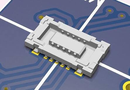
I ordered some samples of these from Molex, and I love them. You could fit a 20-lead connector in such a tiny space… They click together really nicely, and make quite a solid connection.
Nonetheless, in terms of your design I’d use two on the edge rather than one of them in the middle. If you were to push on the edge of the sensor PCB, with the connector in the middle like that, I think you’d run the risk of unseating the connection.
Either that or add some mounting holes so the sensor board can be screwed down in addition to clicking it in…
Would you make the connector orientation-less (i.e. duplicate the signal lines on each side, so it doesn’t matter which orientation you plug in the sensor board)? Because the connectors aren’t keyed, you can insert them either way round…
And finally I’d also be really interested if you considered the scenario where the sensor isn’t directly connected to the other PCB, but rather via a cable… How you would make the connection then?
That would be my application for these connectors, but since there are no pre-made cables for them, as far as I can tell, one would have to custom order self-designed FPC cables… and that looks like it would be quite expensive until you get into high volume… do you have any thoughts on that?
Ok, Ill think about that. I did not plan for the sensor to be direction-less, that’s why I made the small nudge in the corner. There should naturally be a marking on the bottom silkscreen where the sensor will be mated.
On another note, Im thinking to make the sensor breakout even smaller, and have two versions. One version for steppers with the SPI and ABZ interface broken out, and another for BLDC with the UVW broken out, if someone needs that at some point. The BLDC type should IMO have mounting holes, for better integration with a BLDC, but for the stepper design I’m relying on the “High Retention Force”.
These are the ones I was looking at. I agree the, form factor is nice
Another choice would be to simply break out all the pins (14 contacts, not 10), but that will be a cost increase.
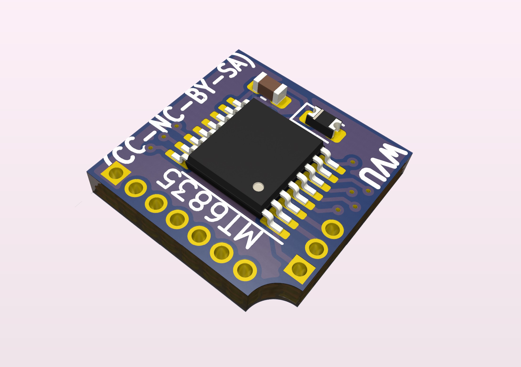
In relation to the calibration procedure, the datasheet for the TM6835 describes how one can use the PWM pin for that, but also states that the SPI interface can be used, so I do not have the PWM pin broken out?
How about a small board with the connector and holes to solder a ribbon cable? Use ribbon cable pitch for the holes on the sensor board too, so it can either be clicked on directly or add the cable+connector board.
This is without the 1.27 headers. Just the high-retention-force connector (10 pin).
Since the mating height is 0.7mm there should be room for 0603 caps or resistors in the space between the board and the breakout. The TVS diode may change, so that should probably be located on top, dependent on height.
I’m curious about the need for resistors on the com lines? @Roger_Mao
Edit: Here the Diode is topside. Although the D_SOD-523 package is very compact, it still looks better and possibly it is more suitable with a larger diode or another footprint dependent on current stock.
Yes, good idea, that would be for the other version.
The idea behind this SlimStack breakout board is to have perfect alignment each time. I know that depends on the magnet, but with a good mounting technique for the magnet, I think we can get good repeatability.
You can always design for solder connections, but this doesn’t solve the problems I’m trying to solve. For me the aim is very much to avoid soldering… if you want to solder, you don’t need to bother with any of these connectors…
For my sensors I use JST-SH 1.0 connectors, which are fairly small, can only be inserted one way, and there are plenty of cheap pre-made cables available to order on AliExpress and other sites. For I2C it is even a “standard” (StemmaQT/Qwiic).
But for many purposes JST-SH is still quite big, especially if you think about breaking out all the interfaces offered by a powerful sensor like the MT6835… That would come in at around 12 or more signal lines, and even in JST-SH this uses a lot of space. Also the JST-SH are more than 2mm tall in the horizontal version.
The attraction of these Molex connectors (the ones Juan-Antonio has chosen are marginally larger than the ones I linked) is that they are fairly cheap, really tiny, and available for 20 signals or even more… They mate very well and make a solid connection that should be sufficiently vibration-proof for the type of designs I work on. They are SMD parts, come on reels, and can be mounted in PnP assembly processes.
The only downside is that there’s no pre-made cables (AFAICT), and making such cables will be expensive, unless you make 10000 at a time…
Found these LM5106 TI drivers rated for 100V w. single_pin PWM interface. So 4 is needed. They are relatively fast They have programmable dead_time_insertion through a resistor (100ns to 600ns).
it looks good. But how will you set the alignment between the sensor, the magnet and the motor rotor? I spent the whole weekend installing an encoder on a stepper motor, but I didn’t get a result. In a closed cycle, the rotor is blocked immediately. In the open rotates without problems. With the help of conductors, I installed a magnet and a sensor on a brushless motor. I controlled the motor in an open loop cycle and monitored the encoder readings, the difference reaches up to 0.2 radians. For a stepper motor, this is already critical
I suppose thats what the calibration does in the MT6835?
The Molex connector is centered on the SHAFT! of the NEMA23, so I think sensor and magnet alignment should be possible. How to Aleigh the rotor to sensor readings is a good question. I suppose you move to a given micro-step and cero the sensor?
Since I have some faith in the SAME51 still, I made a small sketch of a FunQi board stack.
Unfortunately the USB pins are on the QDEC pins in the 64pin package, and thats the only one. I guess the only alternative is SPI or Interrupt_based Encoder lib, which possibly puts strain on the MCU. @nikolaewich1988 Which sensor did you use? Was it via SPI interface ?