Expanded to 30mm. on the narrow part. This will give some room around the 25mm Portenta. Room for cover.
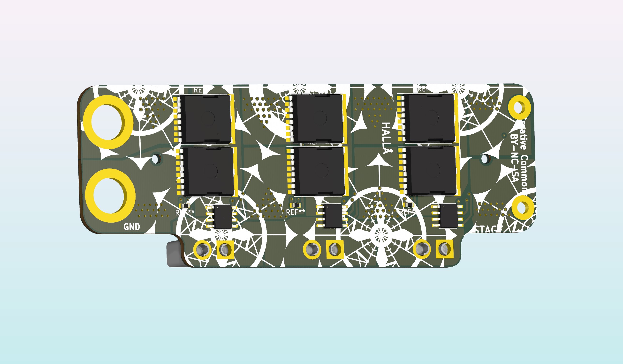
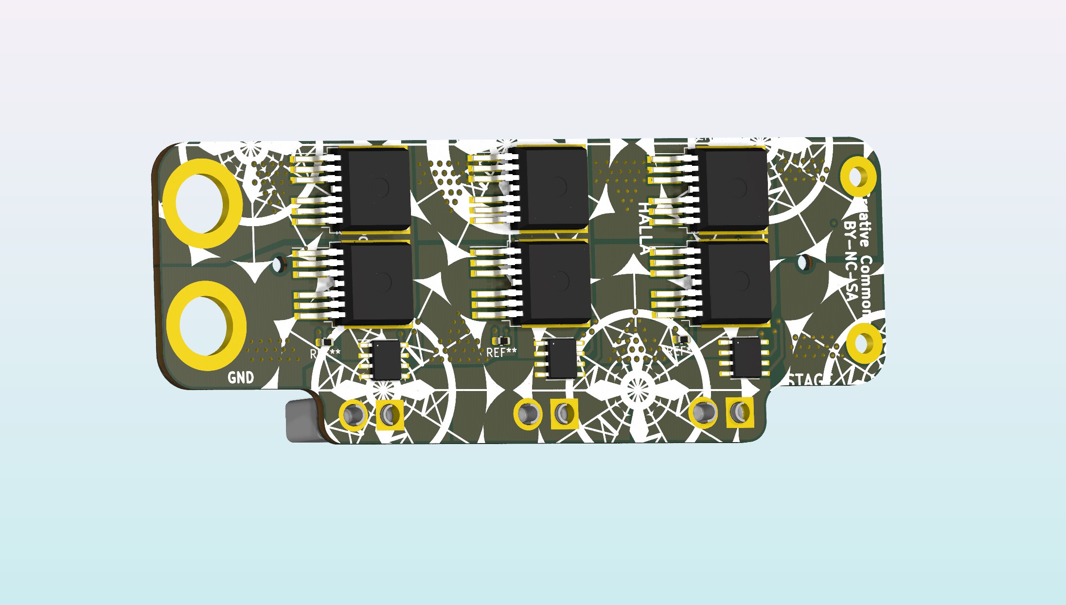
Same concept, just TO-263-6 footprint.
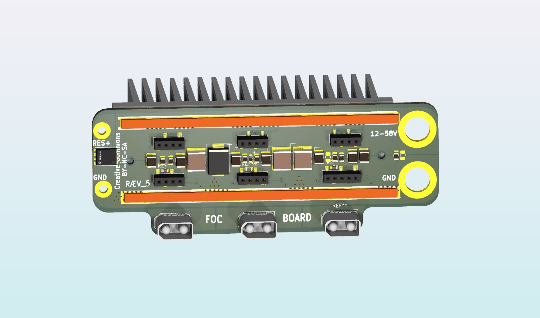
PG-HDSOP-16-2, These has a top_cooling plate.

Modular Capacitor;
Mounted with 1mm Copper bend clip. If more capacitors are need, one can just expand the PCB.
You probably want to cover those solder joints on the caps.

Added 2x SMD CAP to remove the possibility of short´s between wire lug and CAP_MODULE. I suppose shielding is still in place, for good order.
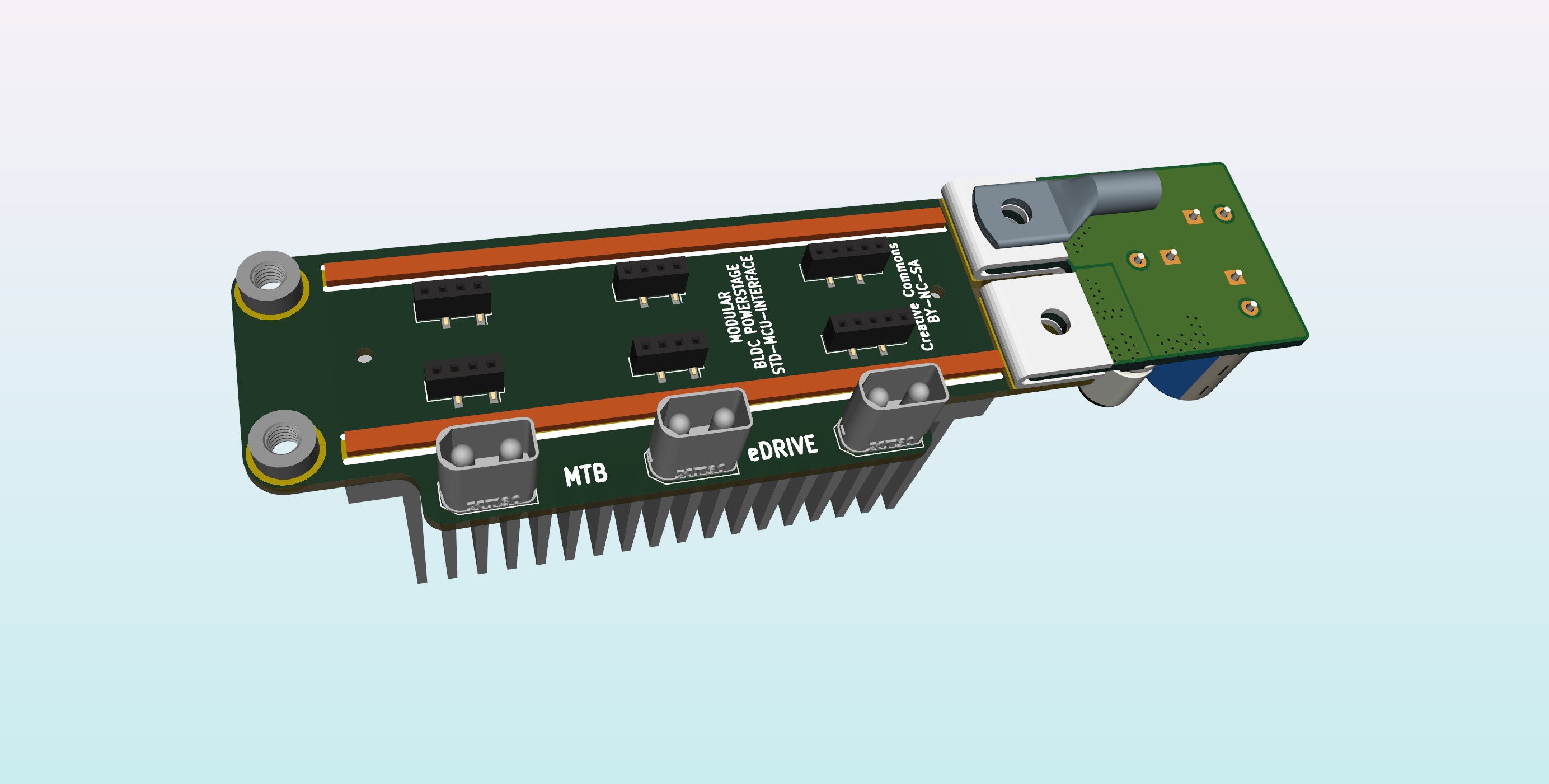
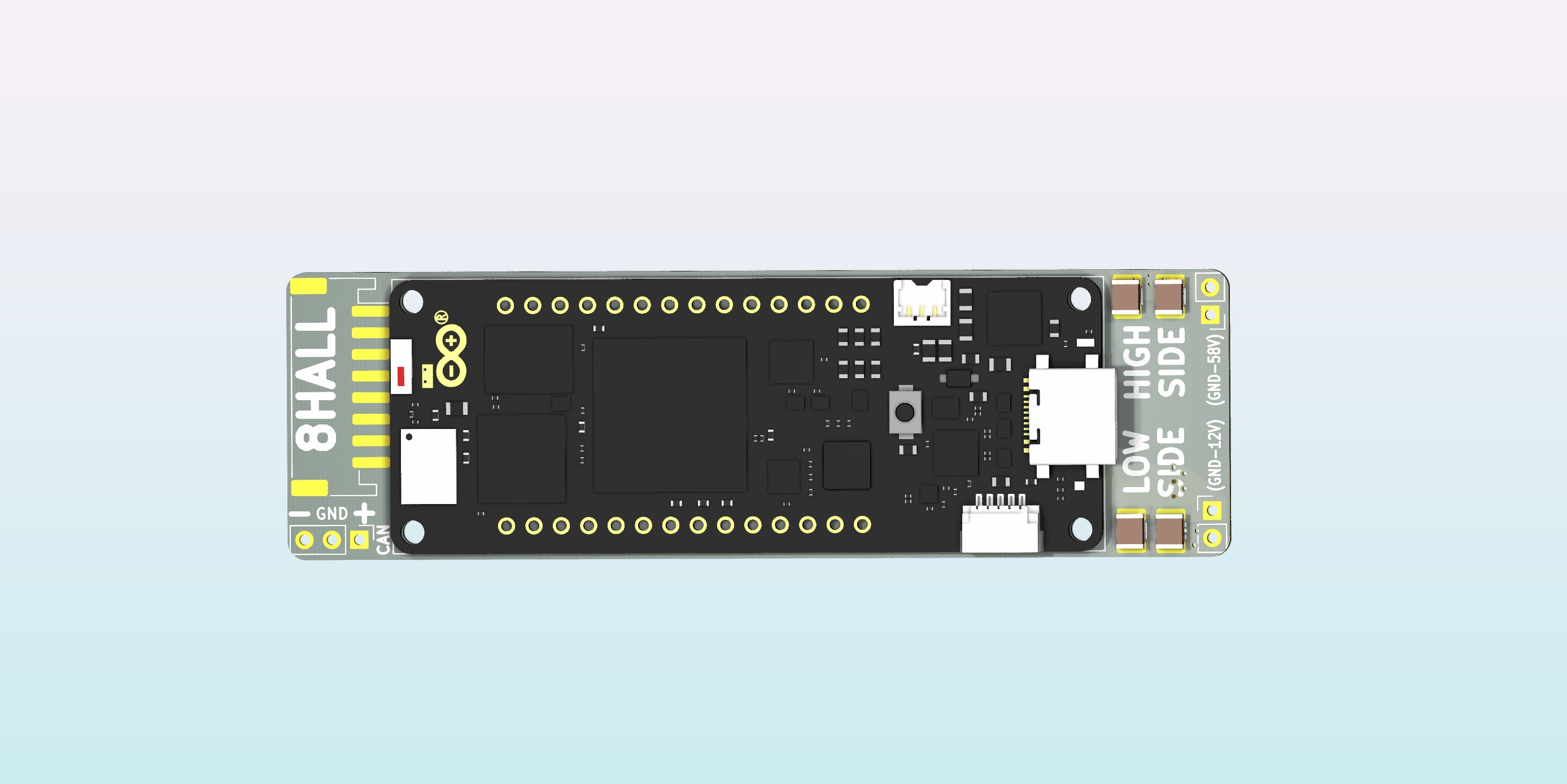
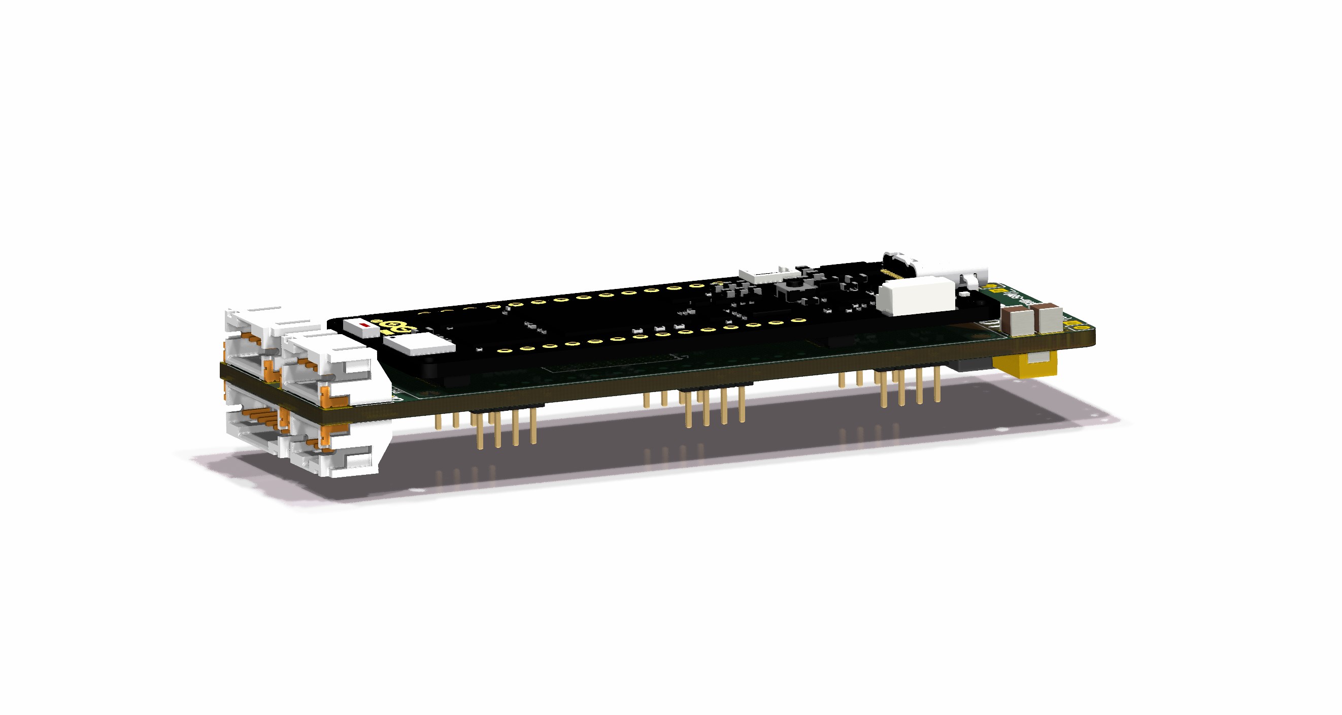
Here is the Portenta H7 outlined. Moved 2mm headers a bit to make room for step_down_circuit (coil)

Nice design. Thank you for sharing.
Thx, here is the repo for future reference: Juanduino/MTBeDRIVE (github.com) @themoment the design is still changing. Just found room for a JST (HALL) connector. I ques those are mandatory.

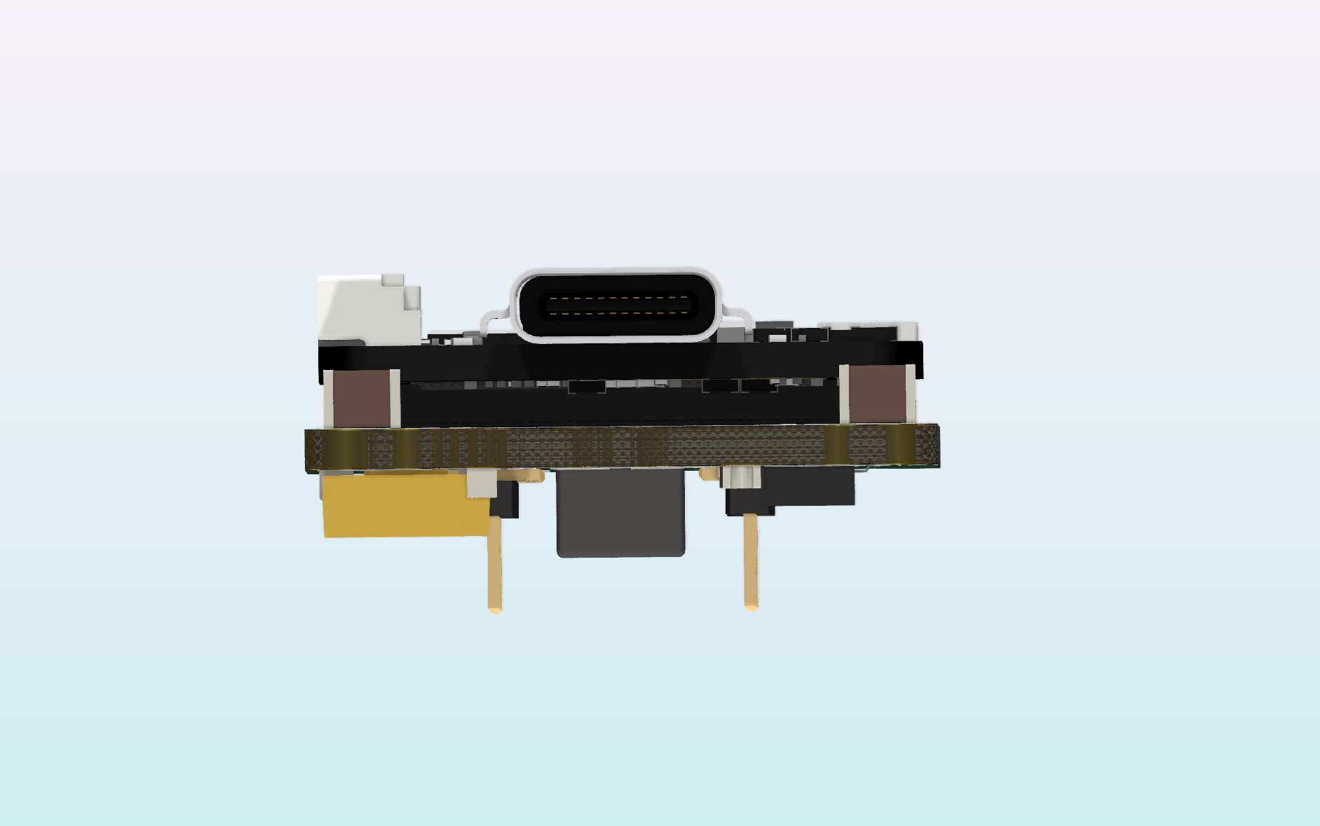
The Tantalum capacitor is around 2.5mm tall. It should fit above the busbar.

Looks great, any progress on this? It’s been a few years I guess…