Greetings all,
Hope everyone is doing well.
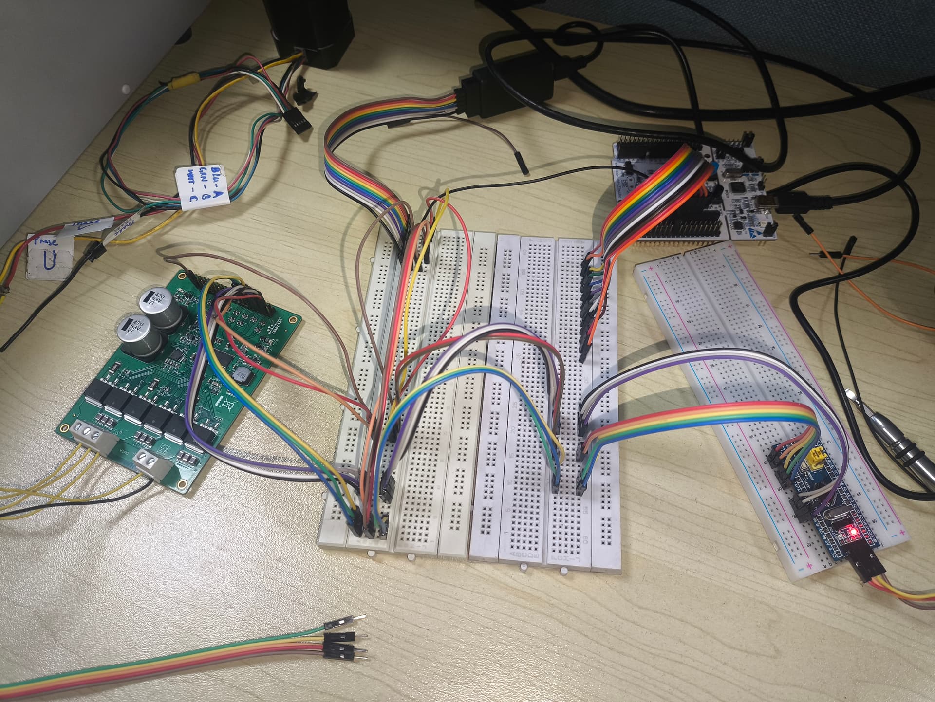
I have been using (learning) the simpleFOC library implementation and I was able to run the 24V BLDC motor I have. It’s a basic setup with Arduino Uno and a DRV8301 (ZonRi, AliExpress) driver board. I didn’t set the pwm_frequency variable for the driver, and I was getting PWM at frequency 5kHz. This is in velocity_openloop mode. I was able to run the motor in position_openloop modeand hall-based closed-loop in torque, voltage mode.
Somehow, I ended up damaging my D3(~) and D4 pins. Also, current-sensing hasn’t been implemented for Arduino so I had to move on anyway, and try the STM32 Nucleo-64 that I have (F410RB).
First few tries:
GVDD_UV fault on the DRV8301. Had also chosen TIM5 for PWM and got PWM frequency of around 400 Hz. Realized it can’t give frequency high enough (maybe it can) for motor control and that could be causing the issue. I just moved on and chose pins connected to TIM1
With TIM1:
- PWMs still had similar low frequency. Set the
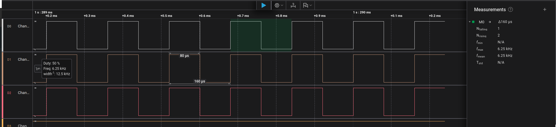
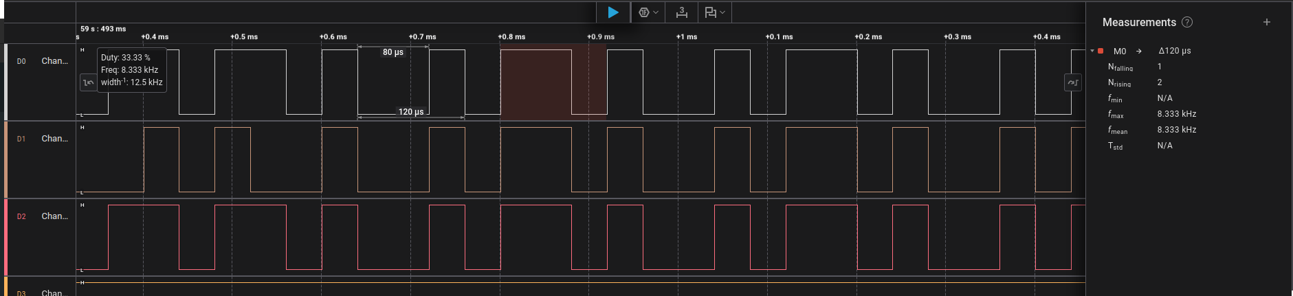
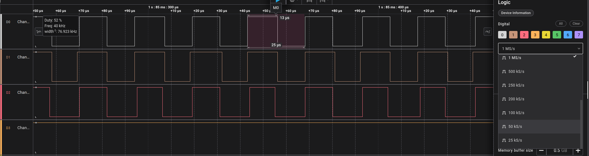
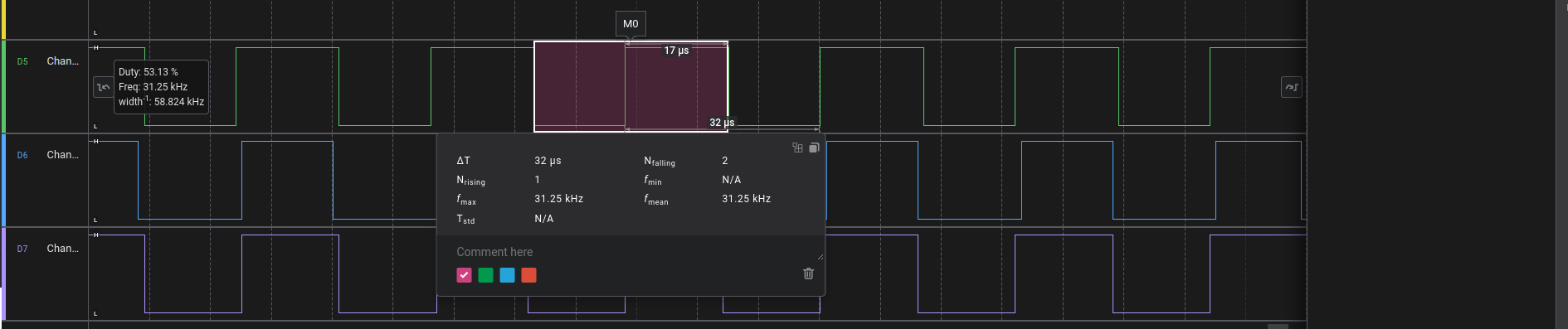
driver.pwm_frequencyvariable at 20,000 and got around 6.25 kHz of pwm, Increased it to 40,000 and got around 8.333 kHz. GVDD_UVfault: This was happening cause for some reason the DRV8301 is drawing too much current. Solution: Increased the current limit on the power supply. The power supply goes into current control mode with current reaching the max set limit and voltage dropping from 24V to as low as 8V. And the motor just shakes - oscillates with a very tiny angular displacement. You can barely notice it. But you can easily feel the heat, the motor gets really hot in under a minute.
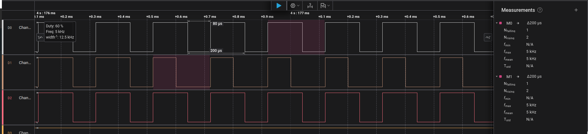
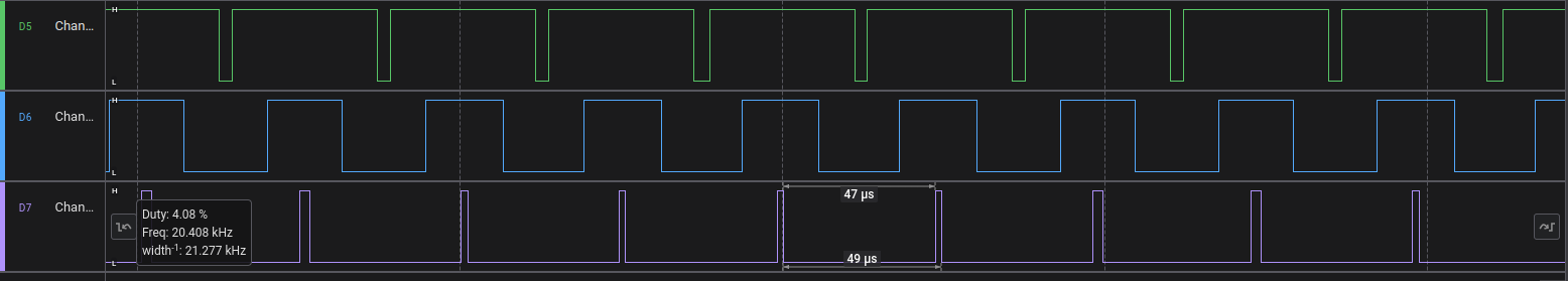
Now, the PWM waveform being generated by the Nucleo is also a little weird looking. While the ones generated by the Arduino very even (almost 50% duty), the ones from the Nucleo are not symmetric. I tried a Bluepill (F103C8T6) as well, to generate the PWMs (didn’t connect the driver/motor) and got similar PWM waveforms.
As a new user, I am unable to add more media (images) to my post. So I will add the waveform snapshots from my logic analyser as replies to this post.
The same firmware is being flashed on the three boards. Making sure to change the pins accordingly and have added the pwm_driver.pwm_frequency line for the STM32s:
#include <SimpleFOC.h>
#include <DRV8301.h>

// #define INH_A PA_0  // TIM5
// #define INH_B PA_1  // TIM5
// #define INH_C PB_11 // TIM5

#define INH_A PA_10 // TIM1 D2
#define INH_B PA_8  // TIM1 D7
#define INH_C PA_9  // TIM1 D8

#define EN_GATE PB_5
#define nFAULT  PC_7

#define SCLK  PA_5  // SPI Sync Clock
#define nSCS  PB_6  // SPI Chip Select (SS - Slave Select)
#define SDI   PA_7  // Serial Data Input  (SPI MOSI)
#define SDO   PA_6  // Serial Data Output (SPI MISO)

// BLDCMotor(int pp,  float R = NOT_SET, float KV = NOT_SET, float L = NOT_SET);
// for Delta connection, R_phase = R_line * 1.5 = 0.8 * 1.5
// Bemf Constant = 2.71 Vrms/ KRPM
// KV = 1/K_Bemf = 1000/2.71 = 369 RPM/V + 10% = 405.9 RPM/V
BLDCMotor motor = BLDCMotor(4, 1.2, 405.9);

BLDCDriver3PWM pwm_driver = BLDCDriver3PWM(INH_A, INH_B, INH_C);
// DRV8301 gate_driver = DRV8301(MOSI, MISO, SCLK, CS, EN_GATE, FAULT);
DRV8301 gate_drv = DRV8301(SDI, SDO, SCLK, nSCS, EN_GATE, nFAULT);

float target_velocity = 2; // [rad/s]

// utility function enabling serial communication with the user to set the target values
// this function can be implemented in serialEvent function as well
void serialReceiveUserCommand()
{
    // a string to hold incoming data
    static String received_chars;

    while (Serial.available())
    {
        // get the new byte:
        char inChar = (char)Serial.read();
        // add it to the string buffer:
        received_chars += inChar;
        // end of user input
        if (inChar == '\n')
        {
            // change the motor target
            target_velocity = received_chars.toFloat();
            Serial.print("Target velocity ");
            Serial.println(target_velocity);

            // reset the command buffer
            received_chars = "";
        }
    }
}

void setup()
{
    Serial.begin(115200);
    SimpleFOCDebug::enable(&Serial);

    // power supply voltage [V]
    pwm_driver.pwm_frequency = 40000;
    pwm_driver.voltage_power_supply = 24;
    pwm_driver.init();
    // pwm_driver.enable();

    gate_drv.begin(PWM_INPUT_MODE_3PWM);


    motor.linkDriver(&pwm_driver);    // link the motor and the driver

    // limiting motor movements
    motor.voltage_limit = 1;   // [V]
    motor.current_limit = 2;
    // motor.velocity_limit = 20; // [rad/s]

    // open loop control config
    motor.controller = MotionControlType::velocity_openloop;

    motor.init();

    Serial.println("Motor ready!");
    _delay(1000);
}

void loop()
{
    // open loop velocity movement
    // using motor.voltage_limit and motor.velocity_limit
    motor.move(target_velocity);

    int allFaults = gate_drv.read_fault();
    Serial.println(allFaults);

    // receive the used commands from serial
    serialReceiveUserCommand();
}
Please help me in figuring out the problem here.
Why are the STM32 boards unable to make the DRV8301, drive the motor?
Also, why is the PWM frequency not increasing according the code? At 20,000, I barely get 6,000.
Thank you for taking the time to read. Feel free to leave any suggestions you have or doubts regarding the setup, I will be happy to explain.
Warm Regards
Unable to get the serial debug output for the bluepill. Maybe cuz I am using the ST-Link to connect to the bluepill and would need to connect separate UART pins for the serial.
– elemomanYes - if your bluepill has USB you can use that for debug serial… but sometimes bluepills only have 64kB flash and can’t fit everything
– runger