Motor works with Arduino Uno but not with STM32 Nucleo-64 (DRV8301, velocity_openloop)

This behaviour is strange.
What you could expect to have is:

  • Low speeds: the motor runs pretty smoothly (depending on the cogging and the motor construction)
  • Mid speeds: the motor can follow but has very low torque, basically if you hold it by hand you can stall it easily
  • Higher speeds: The motor cannot follow. It basically just vibrates in place

So with all that is happening it makes me wonder if all of your mosfets are outputting correctly. The behaviour looks very similar to the behaviour of one phase not being powered.
Could you probe the motor connectors with your scope, rather than the MCU pins?

Hey @Antun_Skuric

So I have connected the analyser jumper pins at the interconnect of the driver and the Nucleo board:

DIO 0, 1 and 2 are the high side A, B and C and DIO 3, 4 and 5 are the low-side counterparts:

Here’s a video of the motor as I go from speed 1 to 30.

I noticed that this time around it started rotating at speed 11 and went up to 27 while rotating. Was oscillation below 11 and from 28 onwards. (velocity_openloop control, 6 pwm mode)

The motor phases are soldered to the wires connected with the driver board:

It really seems to me like one phase is not powered. Is there a way you can plot the pwm sent to the motor?
The output of the MOSFETs?
The nucleo waveforms look good.

Hey @Antun_Skuric

When it does rotate that in that 11-27 speed range, at that point all the MOSFETs must be triggering, right?

I took the voltage drop across each source-drain while in operation (both oscillating and rotations) and found it to be 3.6-3.7 V. Mosfet Datasheet

Next I just manually held the logic analyser pin at each of the MOSFET gate pins. DIO6 is the new pin:

MOSFET 1: HIGH_C (DIO6 matches with DIO2)

Here, it’s matching with DIO2 and that is High-side C. I couldn’t help but notice the weird spikes on DIO0, DIO1 and DIO5:

They happen exactly when DIO2/6 end. Must be something cuz of me connecting the logic analyser pin..?

MOSFET 2: LOW_A (DIO6 match with DIO3)

No spikes.

MOSFET 3: HIGH_A (?)

  • It resembles DIO0 most closely but it’s slightly wider.
  • On connecting the logic analyser pin to this MOSFET’s gate, I heard a few whiny beeps and the OCTW LED kept flickering.
  • Motor also instantly goes into vibrations when I connect the analyser pin to this gate.

MOSFET 4: LOW_B (DIO6 matches with DIO4)

Normal, like MOSFET 2: LOW_A

MOSFET 5: HIGH_B

Closest match with DIO1. Similar behavior as to HIGH_A. Motor vibrates and the OCTW LED flickers.

MOSFET 6: LOW_C (DIO6 matches with DIO5)

So had that weird OCTW flickering on HIGH_A and HIGH_B but interestingly, none upon connecting the logic analyser pin with the gate of HIGH_C. Other than that the waveforms seem to be matching.

These waveforms are taken during when the motor is properly rotating at speed command 20. Next post, I will share waveforms at speed 6 when it’s oscillating.

Speed 6. Motor is oscillating.

MOSFET 1: HIGH_C

DIO6 has a significant delay compared to the MCU DIO2

MOSFET 2: LOW_A

Matches perfectly.

MOSFET 3: HIGH_A

The motor is already vibrating. Upon connecting the analyser pin to the gate of HIGH_A, it’s vibration amplitude becomes smaller but it continues to vibrate. OCTW LED flickers, as previously. That tiny beeping sound also occurs.

MOSFET 4: LOW_B

MOSFET 5: HIGH_B

OCTW LED flickers, motor still vibrates but with lesser angular displacement. Also, DIO3 and DIO4 (LOW_A and LOW_B) look very similar too…

Without the analyser pin connected to the gate:

There are periods when the signals look very similar…maybe that explain the problem (these are MCU waveforms). Is this the problem maybe? The MCU is not generating the correct waveforms..?

MOSFET 6: LOW_C

While checking that HIGH_B MOSFET, I think have stumbled on something useful… the MCU is maybe not generating the correct waveforms? There’s a few pulses which are correct and then a few where they are not distinct?

I will let you guys have a think :man_bowing:

Actually, if the motor does not turn smoothly on the low speeds but does on higher that could mean that one phase is not triggering and when it comes to the faster rotation the motor’s inertia allows for the full rotation, even though on voltage phase is not used. For low velocities there isn’t enough of inertia for the motor to turn.

You could also try disconnecting one phase of the motor (maybe one at the time) and see if the same behavior persists even without one phase connected.

Disconnected phase A : similar behavior

Oscillates below 10 and spins until 24. But the oscillation is different: it looks as if there is some intention (? I don’t know a better way to describe it lol) as it moves back and then forth. With all three phases connected as you might have seen in the video, it goes back (intentionally) and then snaps forth. It doesn’t move forwards, it kind of snaps to the forward position.

Here’s a video of the current oscillation at speed 1: link.

Beyond that it tries to spin but it doesn’t oscillate. It does some half or quad rotations and sometimes even full 2-3 loops and then reverses direction and yea. It’s not regular oscillation, or even periodic. Video.

Disconnected phase B

It just vibrates. Oscillations with very tiny amplitude. Frequency of oscillation increases as I increase the speed command.

Disconnected phase C

Same as phase B disconnection, vibrations!

Safe to say, I am very confused @Antun_Skuric ! :sob:

Huh, it’s a mysterious one! :smiley:

So, this might confirm that the phase A is not well driven, that it is connected to GND constantly, or high-impedance maybe…

But it’s really strange that it only happens with stm boards and not with Arduinos.

What if you connect all the motor phases and rize the voltage limit to 2V (also use only the pole pairs number - no KV rating or the resistance - it will make the debugging easier and help isolate the problem)

Ok, got some interesting results

  • Vibrates upto speed 24
  • And then rotates smoothly from 26 till 76 (but you have to increase gradually, like from 50 → 60 →70→75).
  • If I jump from 30 (or 0, or any lower speed) to 70 it’s fine, but directly to 71 or any value above it results in oscillations.
Code
#include <SimpleFOC.h>
#include <DRV8301.h>

#define INH_A PA_10     // TIM1_CH3 | D2
#define INH_B PA_8      // TIM1_CH1 | D7
#define INH_C PA_9      // TIM1_CH2 | D8

#define INL_A PB_1      // TIM1_CH3N | CN10 - 24
#define INL_B PB_13     // TIM1_CH1N | CN10 - 30
#define INL_C PB_0      // TIM1_CH2N | A3

#define EN_GATE PB_5    // D4 
#define nFAULT  PB_3    // D3

#define SCLK  PA_5      // D13 | SPI Sync Clock
#define nSCS  PB_6      // D10 | SPI Chip Select (SS - Slave Select)
#define SDI   PA_7      // D11 | Serial Data Input  (SPI MOSI)
#define SDO   PA_6      // D12 | Serial Data Output (SPI MISO)

BLDCMotor motor = BLDCMotor(4);

BLDCDriver6PWM pwm_driver = BLDCDriver6PWM(INH_A, INL_A, INH_B, INL_B, INH_C, INL_C, EN_GATE);
// DRV8301 gate_driver = DRV8301(MOSI, MISO, SCLK, CS, EN_GATE, FAULT);
DRV8301 gate_drv = DRV8301(SDI, SDO, SCLK, nSCS, EN_GATE, nFAULT);

float target_velocity = 2; // [rad/s]

// utility function enabling serial communication with the user to set the target values
// this function can be implemented in serialEvent function as well
void serialReceiveUserCommand()
{
    // a string to hold incoming data
    static String received_chars;

    while (Serial.available())
    {
        // get the new byte:
        char inChar = (char)Serial.read();
        // add it to the string buffer:
        received_chars += inChar;
        // end of user input
        if (inChar == '\n')
        {
            // change the motor target
            target_velocity = received_chars.toFloat();
            Serial.print("Target velocity ");
            Serial.println(target_velocity);

            // reset the command buffer
            received_chars = "";
        }
    }
}

void setup()
{
    Serial.begin(115200);
    SimpleFOCDebug::enable(&Serial);
    
    // driver config
    // power supply voltage [V]
    pwm_driver.pwm_frequency = 20000;
    pwm_driver.voltage_power_supply = 24;
    pwm_driver.init();

    gate_drv.begin(PWM_INPUT_MODE_6PWM);
   
    motor.linkDriver(&pwm_driver);    // link the motor and the driver

    // limiting motor movements
    motor.voltage_limit = 2;   // [V]
    // motor.current_limit = 2;
    // motor.velocity_limit = 20; // [rad/s]

    // open loop control config
    motor.controller = MotionControlType::velocity_openloop;

    // init motor hardware
    motor.init();

    Serial.println("Motor ready!");
    _delay(1000);

    Serial.print(gate_drv.drv8301_read_reg(DRV8301_CONTROL_REG1));
    Serial.print("\t");
    Serial.println(gate_drv.drv8301_read_reg(DRV8301_CONTROL_REG2));
}

void loop()
{
    // open loop velocity movement
    // using motor.voltage_limit and motor.velocity_limit
    motor.move(target_velocity);
    // Serial.print(gate_drv.drv8301_read_reg(DRV8301_CONTROL_REG1));
    // Serial.print("\t");
    // Serial.print(gate_drv.drv8301_read_reg(DRV8301_CONTROL_REG2));
    // int allFaults = gate_drv.read_fault();
    // Serial.print("\t");
    // Serial.println(allFaults);

    // receive the used commands from serial
    serialReceiveUserCommand();
}

So the speed range just increased..?

Edit: Also at standstill, the braking current (if that’s what it’s called) is also slightly higher - the DC supply shows 0.25 A. It’s 0.03 A if the voltage_limit = 1;

Hey @Antun_Skuric

Thanks for the easy to understand explanations!

I have just tried the 6PWM setup with the Bluepill and sadly it’s working the same was as the F410RB.

Regarding the low-level configuration, I would also like to troubleshoot and debug on my end as much as I can. I have worked with the F410RB prior to this, using the open-source Libopencm3 library and configured timers and all.

My goal is also to understand the FOC implementation so this exercise could help me, even though if not entirely fruitful for the project :sweat_smile: . I have gone through most of the docs - “Writing the code”, “Library Source” in digging deeper and some of the “Theory Lovers Corner”.

If you can share some tips in general, or any pointers as to where I should start looking in the repository, I’d be really grateful!

Thanks!

Hey!

Yeah, so these are some good and bad news simultaneously :smiley:

I really dont know what’s going on. The setup that you have is pretty standard and many people have used it so far. Your motor has a relatively low pole-pair count and that might case issues for low speeds in open-loop. If the cogging torque of the motor is higher than the torque produced by the open-loop. But this should get better with the increase of the motor.voltage_limit.
Do you maybe have a different motor to try?

You’re connecting the common ground right?

You can also try rising or lowering the motor.dead_zone : BLDCDriver 6PWM | Arduino-FOC
By default it should be at around 5% of the PWM duty-cycle.
But it does not make much sense to me, it should work regardless. Less good but it should work. Especially since it is quite frequent component stm32f1/f4 and the drv8301).

Can you please share your final code once again please. I’m gonna run it on my board as well. I don’t have the drv8301 but drv8302 version (no SPI) though.

Hello

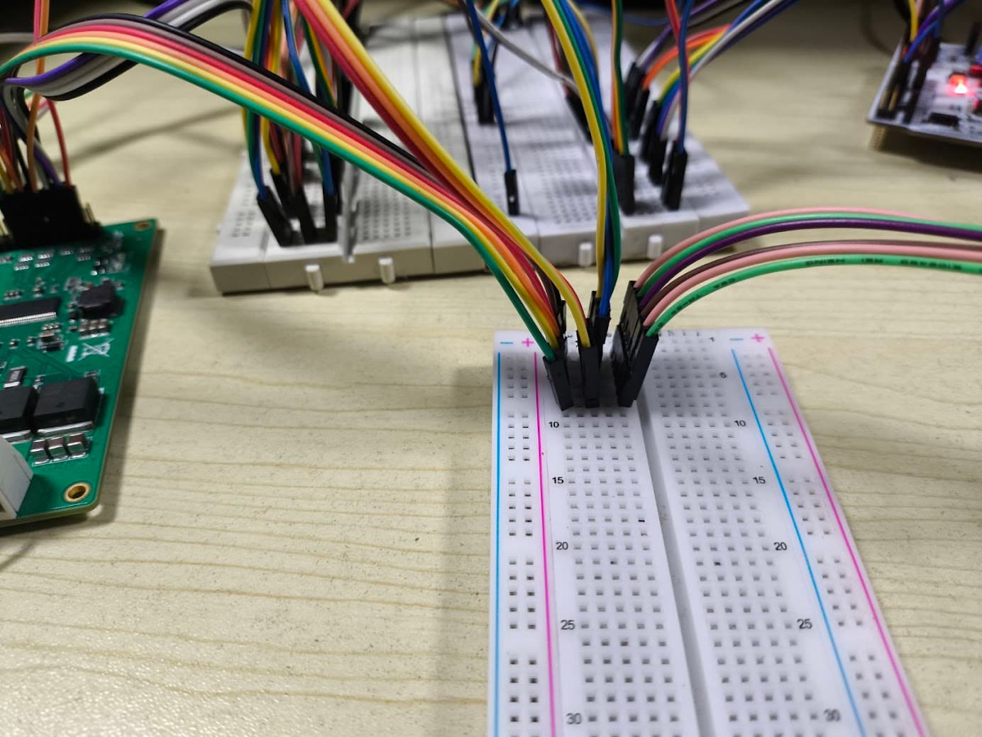
Yes it is a very basic setup and easily working with the Arduino Uno, it’s quite baffling.

I think I may have some generic stepper motors around. I have a 230V PMSM, I don’t think I can test it with the DRV8301 lol.

Yes, the ground of the DRV and the MCU are connected.

I’ll try the dead_zone trick, maybe it works.

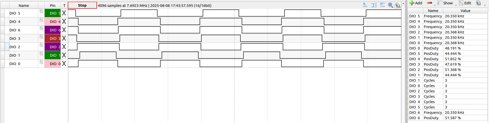
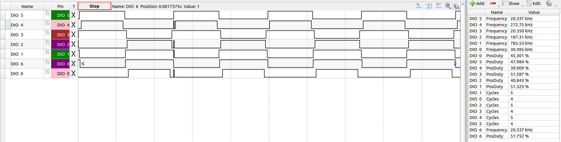
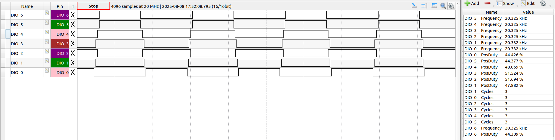
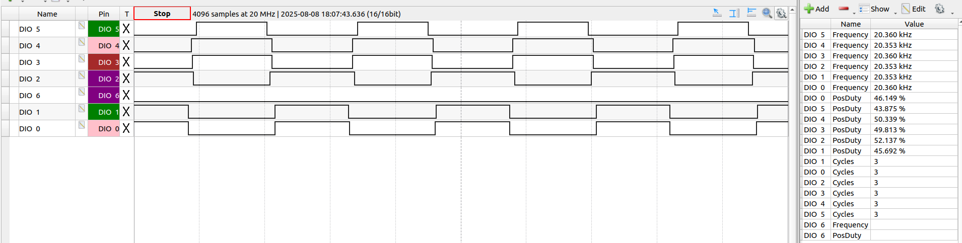
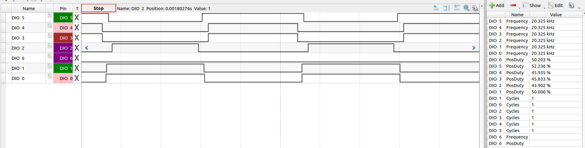
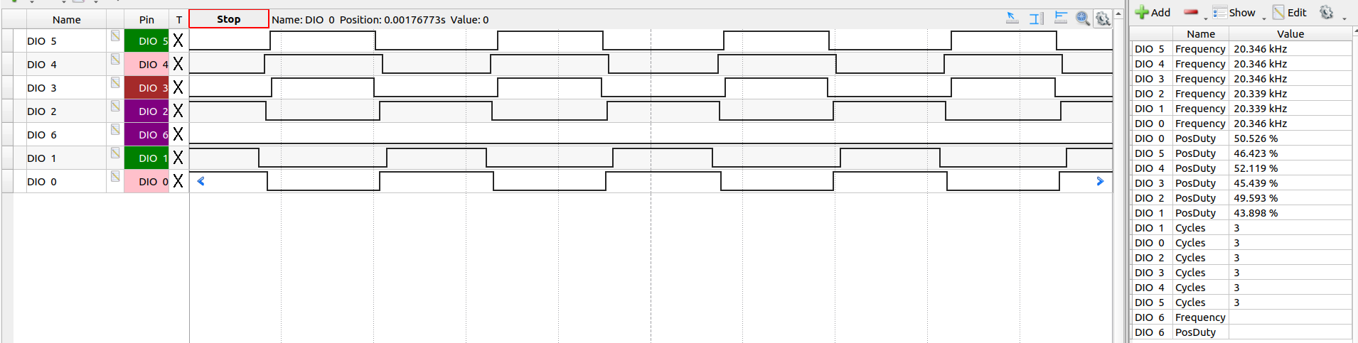
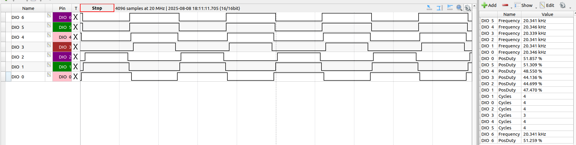
Here, are the velocity_openloop, 6PWM mode codes for the both the Bluepill and the Nucleo:

Bluepill
#include <SimpleFOC.h>
#include <DRV8301.h>

#define INH_A PA8   // TIM1 Ch1
#define INH_B PA9   // TIM1 Ch2 
#define INH_C PA10  // TIM1 Ch3

#define INL_A PB13      // TIM1 CH1n
#define INL_B PB14      // TIM1 CH2n
#define INL_C PB15      // TIM1 CH3n

#define nFAULT  PB8
#define EN_GATE PB9 

#define SCLK  PB3   // SCK1: SPI Sync Clock
#define nSCS  PA15  // NSS1: SPI Chip Select (SS - Slave Select)
#define SDI   PB5   // Serial Data Input  (SPI MOSI)
#define SDO   PB4   // Serial Data Output (SPI MISO)

BLDCMotor motor = BLDCMotor(4);

BLDCDriver6PWM pwm_driver = BLDCDriver6PWM(INH_A, INL_A, INH_B, INL_B, INH_C, INL_C, EN_GATE);
// DRV8301 gate_driver = DRV8301(MOSI, MISO, SCLK, CS, EN_GATE, FAULT);
DRV8301 gate_drv = DRV8301(SDI, SDO, SCLK, nSCS, EN_GATE, nFAULT);

float target_velocity = 2; // [rad/s]

// utility function enabling serial communication with the user to set the target values
// this function can be implemented in serialEvent function as well
void serialReceiveUserCommand()
{
    // a string to hold incoming data
    static String received_chars;

    while (Serial.available())
    {
        // get the new byte:
        char inChar = (char)Serial.read();
        // add it to the string buffer:
        received_chars += inChar;
        // end of user input
        if (inChar == '\n')
        {
            // change the motor target
            target_velocity = received_chars.toFloat();
            Serial.print("Target velocity ");
            Serial.println(target_velocity);

            // reset the command buffer
            received_chars = "";
        }
    }
}

void setup()
{
    Serial.begin(115200);
    SimpleFOCDebug::enable(&Serial);
    
    // driver config
    // power supply voltage [V]
    pwm_driver.pwm_frequency = 20000;
    pwm_driver.voltage_power_supply = 24;
    pwm_driver.init();

    gate_drv.begin(PWM_INPUT_MODE_6PWM);
   
    motor.linkDriver(&pwm_driver);    // link the motor and the driver

    // limiting motor movements
    motor.voltage_limit = 1;   // [V]
    // motor.current_limit = 2;
    // motor.velocity_limit = 20; // [rad/s]

    // open loop control config
    motor.controller = MotionControlType::velocity_openloop;

    // init motor hardware
    // motor.initFOC();
    motor.init();

    Serial.println("Motor ready!");
    _delay(1000);

    Serial.print(gate_drv.drv8301_read_reg(DRV8301_CONTROL_REG1));
    Serial.print("\t");
    Serial.println(gate_drv.drv8301_read_reg(DRV8301_CONTROL_REG2));
}

void loop()
{
    // open loop velocity movement
    // using motor.voltage_limit and motor.velocity_limit
    // motor.loopFOC();
    motor.move(target_velocity);
    // Serial.print(gate_drv.drv8301_read_reg(DRV8301_CONTROL_REG1));
    // Serial.print("\t");
    // Serial.print(gate_drv.drv8301_read_reg(DRV8301_CONTROL_REG2));
    // int allFaults = gate_drv.read_fault();
    // Serial.print("\t");
    // Serial.println(allFaults);

    // receive the used commands from serial
    serialReceiveUserCommand();
}

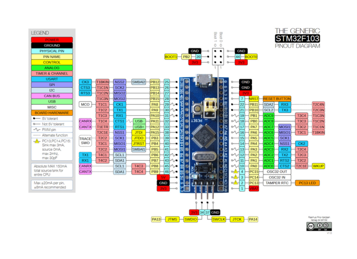
I have configured the Bluepill according to this pin-diagram:
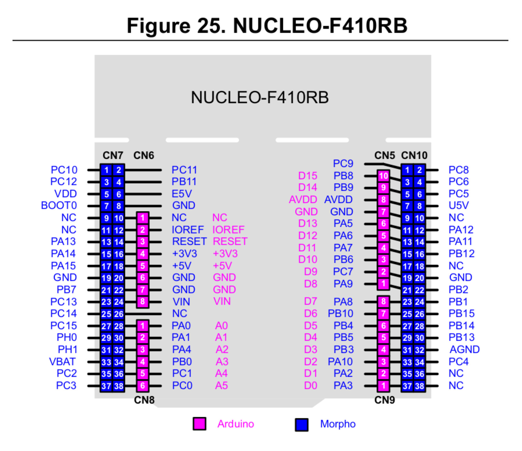
Nucleo F410RB
#include <SimpleFOC.h>
#include <DRV8301.h>

#define INH_A PA_10     // TIM1_CH3 | D2
#define INH_B PA_8      // TIM1_CH1 | D7
#define INH_C PA_9      // TIM1_CH2 | D8

#define INL_A PB_1      // TIM1_CH3N | CN10 - 24
#define INL_B PB_13     // TIM1_CH1N | CN10 - 30
#define INL_C PB_0      // TIM1_CH2N | A3

#define EN_GATE PB_5    // D4 
#define nFAULT  PB_3    // D3

#define SCLK  PA_5      // D13 | SPI Sync Clock
#define nSCS  PB_6      // D10 | SPI Chip Select (SS - Slave Select)
#define SDI   PA_7      // D11 | Serial Data Input  (SPI MOSI)
#define SDO   PA_6      // D12 | Serial Data Output (SPI MISO)

BLDCMotor motor = BLDCMotor(4);

BLDCDriver6PWM pwm_driver = BLDCDriver6PWM(INH_A, INL_A, INH_B, INL_B, INH_C, INL_C, EN_GATE);
// DRV8301 gate_driver = DRV8301(MOSI, MISO, SCLK, CS, EN_GATE, FAULT);
DRV8301 gate_drv = DRV8301(SDI, SDO, SCLK, nSCS, EN_GATE, nFAULT);

float target_velocity = 2; // [rad/s]

// utility function enabling serial communication with the user to set the target values
// this function can be implemented in serialEvent function as well
void serialReceiveUserCommand()
{
    // a string to hold incoming data
    static String received_chars;

    while (Serial.available())
    {
        // get the new byte:
        char inChar = (char)Serial.read();
        // add it to the string buffer:
        received_chars += inChar;
        // end of user input
        if (inChar == '\n')
        {
            // change the motor target
            target_velocity = received_chars.toFloat();
            Serial.print("Target velocity ");
            Serial.println(target_velocity);

            // reset the command buffer
            received_chars = "";
        }
    }
}

void setup()
{
    Serial.begin(115200);
    SimpleFOCDebug::enable(&Serial);
    
    // driver config
    // power supply voltage [V]
    pwm_driver.pwm_frequency = 20000;
    pwm_driver.voltage_power_supply = 24;
    pwm_driver.init();

    gate_drv.begin(PWM_INPUT_MODE_6PWM);
   
    motor.linkDriver(&pwm_driver);    // link the motor and the driver

    // limiting motor movements
    motor.voltage_limit = 2;   // [V]
    // motor.current_limit = 2;
    // motor.velocity_limit = 20; // [rad/s]

    // open loop control config
    motor.controller = MotionControlType::velocity_openloop;

    // init motor hardware
    motor.init();

    Serial.println("Motor ready!");
    _delay(1000);

    Serial.print(gate_drv.drv8301_read_reg(DRV8301_CONTROL_REG1));
    Serial.print("\t");
    Serial.println(gate_drv.drv8301_read_reg(DRV8301_CONTROL_REG2));
}

void loop()
{
    // open loop velocity movement
    // using motor.voltage_limit and motor.velocity_limit
    motor.move(target_velocity);
    // Serial.print(gate_drv.drv8301_read_reg(DRV8301_CONTROL_REG1));
    // Serial.print("\t");
    // Serial.print(gate_drv.drv8301_read_reg(DRV8301_CONTROL_REG2));
    // int allFaults = gate_drv.read_fault();
    // Serial.print("\t");
    // Serial.println(allFaults);

    // receive the used commands from serial
    serialReceiveUserCommand();
}

Timer pins taken from the Alternate Funtion Mapping in the MCU datasheet, page : 40/142

Hope you are able to reproduce the issue! Thanks!

Edit: This is the stepper motor I have. Is it possible to test the algorithm on it?

Yes you can connect the stepper using the hybrid stepper paradigm
(basically you connect the two coils into a common third phase of the motor)
here are the docs.

And here is an example project:

I’ve just tested the code and had no real issues except that the dead-zone in the v2.3.5 is exactly 2x the dead-zone of the v2.3.4. This is due to the fact that the low-level driver has been rewritten completely and this slipped through without us noticing (@runger).
So I’d suggest you to set the dead_zone to 1%

driver.dead_zone = 0.01;

This will make the rotation a bit smoother, but I dont think it will solve the problem.

Huh, its a stubborn problem. :smiley:

There is another thing that you can try to do. It’s not gonna help solving the issue but it might help to debug. You can visualise the current profile with respect to the voltage applied.

There is an example code (in the dev brach) whch turns the motor in the open loop and measures the currents and displays them. The goal being to find which current corresponds to which driver phase. But in your case it could show us what are the waveforms of the currents of the motor and maybe give a bit more insight what is going on:

Here is an example of how to configure the SimpleFOC for DRV8302 current sensing: