Hi all!
I have a problem concerning my setup with a BLDC motor and an Arduino Due running the SimpleFOC lib (V2.2.2).
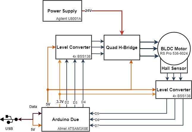
Here is a block diagram of my setup:
My problem now is, that the initialization fails. It says “Failed to notice movement”. The motor shaft is moving about a quarter revolution forth and back multiple times and then stops. On each motor phase I can measured a PWM signal with varying duty cycle and the hall encoders are working perfectly (high or low depending on the rotor position directly measured at the Arduino input). When skipping the initialization the motor is still just vibrating forth and back.
I also tried to turn the shaft manually while initializing, which also fails most of the time. It looks like the hall sensor can’t be read in…
This is my main code:
#include <SimpleFOC.h>

#define PIN_PWM1  2
#define PIN_PWM2  3
#define PIN_PWM3  4
#define PIN_HALL1 7
#define PIN_HALL2 5
#define PIN_HALL3 6

#define NUM_POLES 4

// BLDC motor & driver instance
BLDCMotor motor = BLDCMotor(NUM_POLES);
BLDCDriver3PWM driver = BLDCDriver3PWM(PIN_PWM1, PIN_PWM2, PIN_PWM3);

// hall sensor instance
HallSensor sensor = HallSensor(PIN_HALL1, PIN_HALL2, PIN_HALL3, NUM_POLES);

// Interrupt routine intialisation
void doA(){sensor.handleA();}
void doB(){sensor.handleB();}
void doC(){sensor.handleC();}

// velocity set point variable
float target_velocity = 0;
// instantiate the commander
Commander command = Commander(Serial);
void doTarget(char* cmd) { command.scalar(&target_velocity, cmd); }


void setup()
{
  sensor.pullup = Pullup::USE_INTERN;                 // use internal pullup for hall inputs
  sensor.enableInterrupts(doA, doB, doC);             // initialize sensor sensor hardware
  motor.linkSensor(&sensor);                          // link the motor to the sensor

  driver.voltage_power_supply = 24;                   // power supply voltage [V]
  motor.voltage_sensor_align = 8;                     // motor align procedure voltage [V]

  motor.linkDriver(&driver);                          // link the motor and the driver

 // motor.foc_modulation = FOCModulationType::SinePWM;  // use sinusoidal PWM modulation
  motor.foc_modulation = FOCModulationType::Trapezoid_120;  // use sinusoidal PWM modulation


  motor.controller = MotionControlType::velocity_openloop;  // set motion control loop to be used
  motor.torque_controller = TorqueControlType::voltage;     // set torque control loop to be used

  // velocity PI controller parameters
/*  motor.PID_velocity.P = 0.2f;
  motor.PID_velocity.I = 2;
  motor.PID_velocity.D = 0;*/

  motor.voltage_limit = 10;                           // default voltage_power_supply

//  motor.PID_velocity.output_ramp = 300;               // jerk control using voltage voltage ramp (default value is 300 volts per sec  ~ 0.3V per millisecond)

//  motor.LPF_velocity.Tf = 0.01f;                      // velocity low pass filtering time constant

                                 // use monitoring with serial
  motor.useMonitoring(Serial);

  // INITIALIZATIONS
  driver.init();
  sensor.init();
  motor.init();
  motor.initFOC();

  command.add('T', doTarget, "target velocity");      // add target command T
  motor.useMonitoring(Serial);

  Serial.println(F("Motor ready."));
  Serial.println(F("Set the target velocity using serial terminal:"));
  _delay(500);
}


void loop()
{
  motor.loopFOC();

  motor.move(target_velocity);

  command.run();
}
I also tried to add this code to the FOClib (HallSensor.cpp):
void HallSensor::updateState() {
  SIMPLEFOC_DEBUG("!!!");
  .
  .
  .
But the serial output does not show this line when rotating the rotor!
(Of course i tried the debugging line on another place in the code, which works)
This test code works flawlessy:
#include <Arduino.h>

#define PIN_HALL1 7
#define PIN_HALL2 5
#define PIN_HALL3 6

void doA();

void setup()
{
  Serial.begin(115200);
  attachInterrupt(digitalPinToInterrupt(PIN_HALL1), doA, CHANGE);
}

void loop() {
  // put your main code here, to run repeatedly:

}

void doA()
{
  Serial.println("!!");
}
What can cause that type of problem? How do I find out?
I would be glad for any help!
Best wishes,
Florian
