Did you change to use external?
it’s normal but it is very fast, try to reduce the motor.voltage_sensor_align voltage. Make motor.voltage_sensor_align = 1; Than try.
1 Like
I think it works now!
The initialization does not fail and the motor shaft is blocked!
It’s very interesting:
I used the code suggested from @MoidKhan with external 3k3 pull-ups. I additionall changed the pull-ups to USE_EXTERN in software.
Here the strange part:
it’s only working when i add SIMPLEFOC_DEBUG("!!!"); to the beginning of the function void HallSensor::updateState() in “HallSensor.cpp”.
If I don’t add this line the motor moves stronger and the initialization fails!
How can that happen?
EDIT:
I think I am wrong and it’s stuck in the function because this is the output now:
Connected ...
MOT: Init
MOT: Enable driver.
MOT: Align sensor.
!!!
!!!
Sorry for posting again but the current behavior is the following:
- when initialising the library fails with “Failed to notice movement” and the motor behaves like in the GIF above
- when manually forcing the motor shaft the initialization doesn’t fail but the measured number of PP is of course wrong. But then the motor is spining kind of when I specify a target speed (sometimes just vibrating but that’s I think because of the failed initialization routine)
So i think the reading-in of the hall sensors is working now, but the initialization routine not…
It will most likely help if you specify the PP…
Don’t be sorry for seeking guidance. When new to SimpleFoc it can be a bit challenging to get it all right. I will advise you to go through the docs. You are on the right track!
Ok, but I already set it with BLDCMotor(NUM_POLES) and
HallSensor(PIN_HALL1, PIN_HALL2, PIN_HALL3, NUM_POLES)?
Thanks for that! I wan’t to get the motor working ![]()
Doing motor.initFOC(2.09, Direction::CCW); skipped the initialization and I tried with different speeds but either the motor is running forth and back quickly or doesn’t spin smooth…
Is there a requirement for the hall sensors? Maybe the voltage levels are inverse?
always test the motor in torque control first then switch to velocity and angle. In your code, you have selected velocity_open loop. So, it doesn’t need hall sensor input for commutation. So, I will recommend starting with torque mode and check how the motor behaves.
Regards,
Moid
When using torque control the motor spins quite good and smooth! I didn’t know that velocity_openloop is not using the hall sensors, thanks for that! What does the torque control do? (I have no current sensor installed)
The initialization still fails some time and estimates wrong …
When using velocity control type then the motor is just doing something. So I guess there are still some things wrong
I measured something interesting!
Here it says that each hall sensor should be high for 180°.
I just measured the outputs of the hall sensors of my motor and the are high for about 45°! So that could cause the problem…
Is there a way to confgure for different hall sensors?
Hmm, interesting. Usually they are 120 or 60 degrees apart.
I guess, if true, you need one of the architects to chime in. @Antun_Skuric
Finally something that could cause the problem!
Sounds good, maybe they know how to do it…
In your Datasheet it says 120 degrees. Have you tried to open up the motor ? It also state to be a 8 pole. So maybe it’s 4 PP
If in torque control mode motor is running smoothly, it means that the feedback from the Hall sensor is fine. Regarding the working principle of torque mode, I will advise you to go to the document section where all the explanation is given. ( You require a current sensor if you want to control the motor in current mode for voltage mode you don’t need a current sensor).
In velocity mode, you first need to tune your PID parameter. Once the parameter is tuned then you can run the motor in velocity mode.
At least it means the hall is working but the 45° angle could be very relevant.
I already read that, but it didn’t said if a current sensor is neccessary…
Ok, sounds legit, is there also a ducumentation for it or just the Ziegler–Nichols method?
I also think its 4PP. I can try to open it ![]()
Here are the insides of the motor:
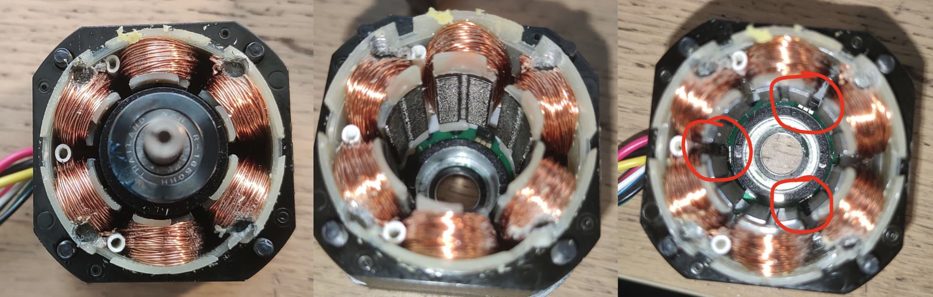
I see 3 pole pairs… and the 3 sensor are sitting in the corners so it makes sense that the only recognize 45° of the rotor
No there is no document for that, try to set PP to 4 and check, how your motor response.
Wait a minute. Are the coils damaged??

I will let buy a new motor!
Thanks all for the help, I will tell you again what the progress is when a new motor arrives.
Did you measure if there is continuity between the phases ?
It does look a bit burned…
Without current sensors I think it’s difficult do drive that motor. It’s only rated for 5 amps.
I measured the following resistances:
R1-2 = 3Ω, R2-3 = ∞, R1-3 = ∞
So, the coil seems to be broken…
That looks like you mounted the motor with bolts that were too long. The first gif you posted shows a 3d printed front plate with 4 c/s bolts that look like they might perfectly line up with the 4 damaged coils.