Yes. I think most of the noise is caused by the pulley on the motor gripping the belt and air is compressed out there. Perhaps you could build some kind of noise damping shield around this area. A V-belt might be better, but then you need an extra couple of pulleys on a shaft to make a reduction of about 1:10. Perhaps a larger motor with larger pulley may also reduce noise.
It might be due to some integrator windup of the speed controller, when you disable it. So when you enable the power to the motor, it will start with full power to motor. You need to set the integrator to zero while the power to motor is disabled.
This is normal for both BDC and BLDC motors. The rotational energy is reversed into the DC power supply causing the voltage to rise. I have used a hardware circuit, that switch in a 5 W wire wound power resistor of 6.8 ohm when the voltage increase above 26.5 V and switch off, when voltage drops below 25 V. I also use two extra electrolytic capacitors on the 24 VDC supply to stabilize the voltage better.
In my case, the IBT_2 H-bridge actually also have some build in over voltage shut down. They turn on the upper transistors, when voltage comes above about 27.5 V. In this way the DC motor gets a short circuit. I think I damaged one IBT_2 by this kind of protection, because this kind of braking current can become very high, because the motor resistance is only about 0.15 ohm. It is better to be able to measure the current and limit the current before this happen.
If you activate the motor very quickly after deactivating it, there is a chance the motor will still be spinning. This will likely throw off the integrators of the PIDs. However, setting the integrators to zero in this case may not always work, because the true value of these integrators won’t always be zero. Additionally, the rough startup could be caused because the target speed is very far away from the current speed, so it will send full power to the motor to accelerate it to the target speed. Another reason could be incorrect disabling logic which disables sensor readings, which will mean when the sensor is re-enabled, the speed could be wrong initially.
For the current loop, the integrator should initially be set so the output of the PID is equal to the back EMF of the motor, otherwise the control loop might become unstable. This is easily done by setting the integrator to zero when the motor is stopped, however it likely requires some sort of phase voltage sensing to do properly when the motor is rotating. Since my boards do not have phase voltage sensing capability, I haven’t been able to get on the fly startup working properly yet. I’m currently looking at possible ways to get around this limitation without using phase voltage sensing.
In my implementation, where I reset the current integrator to zero on start up, if the motor is already spinning it results in the control loop becoming unstable and a huge current spike occurs. The duration of this current spike is around 200us, which is also similar to the current PID loop response time. The magnitude of the current spike is correlated to the speed of the motor.
For the speed loop, the integrator should initially be set so the output of the PID is equal to zero. This can be done by solving the PID equations for the value of the integrator, given the PID output is zero, the input is the current speed, and the target speed is also the current speed.
I suggest that you don’t disable the motor, instead switch between the speed regulator and the current regulator (keeping the current regulator always active). To “disable” the motor, simply switch to the current regulator and set the target current to zero. This will produce effectively a disabled motor. To re-enable, switch to the speed regulator and set the integrator of the speed regulator as described above. This approach should ensure a smooth startup without having to add 500ms delay.
Another way of fixing the power supply voltage rise is to use a beefy TVS diode across the power rails. Choose a TVS diode with a breakdown voltage around 10% higher than your maximum supply voltage. Make sure that it can handle the power dissipation of the large motor, you may need to parallel multiple TVS diodes to achieve this.
The advantages of this method over the resistor is that it does not need an additional control circuit, and it also does not introduce additional ripple into the circuit. However large TVS diodes are a lot more expensive than large resistors, so this solution would only be suitable for small and medium sized motors.
Thank you for the great suggestion. With this solution, the motor can now be switched off perfectly.
I’m not sure about the overvoltage protection yet.
A Meanwell UHP-500-24 will be used for the power supply. According to the power supply’s data sheet, overvoltage protection is already integrated: Meanwell UHP 500-24
How does this overvoltage protection work and is it sufficient?
Unfortunately the overvoltage protection on the power supply only shuts down the output voltage of the power supply and does not do anything to absorb the excess voltage. It is intended more to reduce the damage to your circuit caused by internal faults in the power supply which result in excessive output voltage. Therefore it won’t work for this application, and your power supply will blow up if you don’t implement some other way of clamping the voltage spike.
If you are using this power supply, I suggest picking a TVS diode with a minimum breakdown voltage of around 26V. One option is the 1.5KE27A from Littlefuse. This diode has a minimum breakdown voltage of 25.7V, which is higher than the maximum voltage of your power supply by a sufficient margin so it won’t activate under normal operation.
You will need multiple TVS diodes, the datasheet says the diodes maximum steady state power dissipation is 6.5W, divide this by 2 to get a good margin against overheating (3.25W). Estimate the amount of energy that the motor will generate in a single regenerative braking event (joules), and multiply it by the maximum frequency you anticipate the motor will operate like this (hertz), so you get the average power dissipation (watts). Divide this number by 3.25 and round up to get the number of diodes you need to parallel.
Also make sure the peak power dissipation of the TVS diodes isn’t exceeded, but for this application it is extremely unlikely.
One disadvantage of using TVS diodes and a power supply with overvoltage protection is that you might experience false trips of the overvoltage protection, due to the TVS diode not perfectly clamping the overvoltage. This is because the maximum clamping voltage of this TVS diode is 37.5V at 40.5A, and this is higher than the overvoltage trip threshold of your power supply (26.4V minimum). However the actual clamped voltage will be significantly lower if the current is limited. In my experience it is around 10% higher than the breakdown voltage, when operated at 10% of the maximum clamping current.
Using the approach of switching a resistor with a high frequency, you might be able to clamp the voltage more accurately, avoiding this issue.
Another approach to this is to store the excess energy in a capacitor instead of trying to dissipate it through a TVS diode or resistor. The maximum ripple voltage allowed by regenerative braking will be equal to power supply OCP voltage - power supply set voltage. Now using the capacitor energy formula E = 0.5CV^2, and the above voltages, solve for the capacitance required so the difference in capacitor energy between those two voltages is equal to the regenerative braking energy. Round this up to the nearest available capacitor value and add this capacitor to your circuit to absorb the regenerative braking energy.
If using this approach, I suggest including one TVS diode anyway in case you made a calculation error or something unexpected happens. To minimise the capacitance needed, you need to increase the available voltage range. One way is to adjust the power supply set voltage to be lower. You can also use a diode to block the reverse current, in this case the maximum voltage will not be limited by the OCP threshold anymore and will be limited by the maximum motor driver input voltage.
I hope one of these solutions is suitable for you.
Nice to see, that this integrator windup problem got solved by the suggestion from Andrew.
What type of sewing machine do you plan to use the drive for?
I have looked at the datasheet for the motor here:
It seems like the short term max torque is 2.16 NM or perhaps 1.44 NM. With a strong household sewing machine I aimed for 3.5 Nm on main shaft, and then at gearing to motor of about 1:2.4 might be reasonable. But if you do not need high sewing speed, you may like to make a higher gear ratio and then limit the current to reduce the max torque applied to the sewing machine.
The moment of intertia of motor, I = 1080 gcm2 = 0.108 E-3 kgm2. With a max speed of 4000 rpm on motor, the max rotational energy in the motor equals ½ x I x w2 = 9.5 J.
I would guess, that the rotation energy in sewing machine might be the same as the motor, so it makes 19 J in all. So if you convert all this mechanical energy back to DC supply, the power dump device should be able to handle that. It is however a worst case situation, that is not likely to happen often. Furthermore the losses involved in the braking likely will consume a significant amount of this energy.
If you assume a large electrolytic capacitor of 10.000 uF on the 24 V supply, then 19 J would charge it to about 70 V. Therefore you need more than a large capacitor to dump that energy.
I agree with Andrew, that it will be easiest to use one or more transil diodes to dump this energy, and in most cases the power circuit should be able to withstand an over voltage of 30 % like 31 V in this case. In my case the margin was lower, because I wanted to limit the voltage to about 27 V, and then the simpler circuit with transil diodes is less applicable. From the datasheet provided by Andrew, one diode should be able to take a transient non-repetitive power of 500 W in 10 ms. It makes 5 J. Therefore I think 4 of these diodes in parallel should be sufficient to dump the 19 J. The price here is 0.18 euro each: https://www.tme.eu/de/en/details/1.5ke30a-cdi/unidirectional-tht-transil-diodes/cdil/1-5ke30a/
I like your load cell for the pedal. I think it might be easier to use, but is such a cell expensive?
The air pressure sensor I use have an issue with temperature variations, that influence the pressure. I made some software able to adapt changes in pressure due to temperature changes, but it ads complexity. I furthermore use a non-linear element (part of parabola) in software of the pedal pressure signal in order to make the low speed control easier. I made the slope at start 20 times lower than slope at max speed.
I have made a recording of a kick to the pedal as well, and it looks like this. It made a move of 43 degrees on the sewing machine shaft or 452 degrees on motor:
In this case, the controllers mostly work with a current limit mode at +/- 26 Amp. The pedal value is sampled each 10 ms, and it causes the steps you see. At 160 ms the H-bridge is disabled by a condition of a filtered tacho speed signal is below a threshold AND the pedal is at stop position.
Thank you for your great answer. The 1.5KE27A TSC diode is a simple and good solution. These diodes are quite inexpensive. I will buy a few of them and connect them in parallel.
The motor will later drive a Pfaff 138 industrial sewing machine. The maximum sewing speed should later be around 2500 stitches per minute.
I tried to measure the moment of inertia of the sewing machine. In my measurements, the friction of the sewing machine’s mechanics always dominated.
A large part of the energy is probably absorbed by friction during braking.
For this project I am using a €5 load cell. A cheap load cell was the best solution in my case. Industrial sewing machines have a fixed pedal that is connected to the motor drive via a chain or rod. So all I need to do is screw a screw hook into the load cell and then attach the chain to it. My loadcell
Oh, that sounds interesting. What pressure sensor do you use in your project?
In my company we use pressure sensors that internally compensate for temperature deviations.
Load cells also have temperature drifts. But I haven’t seen any major deviations in my tests.
In microcontrollers I like to use lookup tables for calculating non-linear functions. For example, you can use the pedal value as an index and access the table. And as a result you get a value for the motor controller. Lookup Table Generator
Yes, I agree. My calculation is likely a worst case scenario. However, by stressing my machine with repeated brakes, my used dump resistor got hot.
My temperature problem is not caused by the sensor. You got a confined space of air, and when the temperature increase, the pressure increase according to ideal gas law. The confinement is silicone tubing, and it do not expand that much as the air do. I use an Omron sensor, and the typical price is about 7 euro: https://omronfs.omron.com/en_US/ecb/products/pdf/en-2smpp-03.pdf
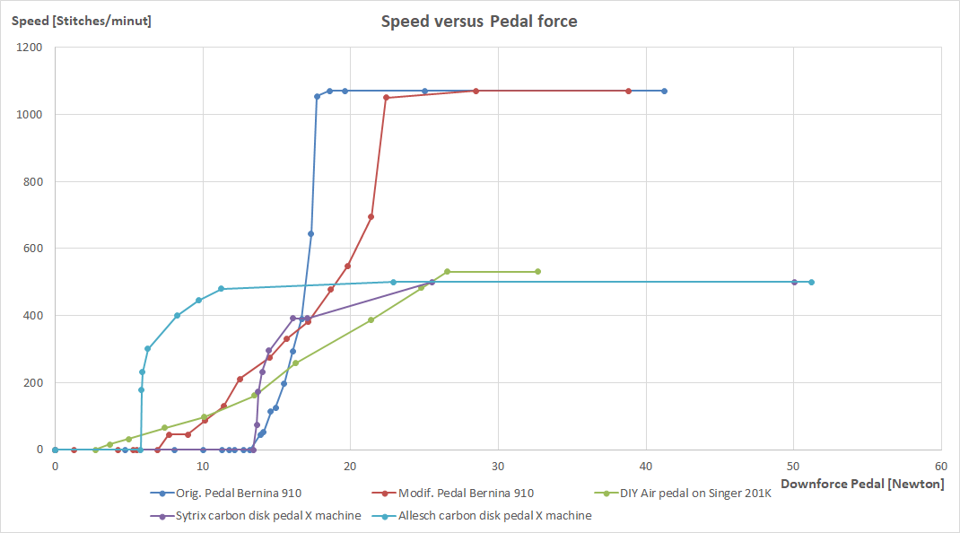
I have set a max speed at a force on pedal of 40 N, and it provides an air pressure of 60 hPa. The motor starts to move at a force of about 4 N.
Elna and Singer made some sewing machines with air pedals back in 1980ies. I guess that it was this temperature problem, that caused them to abandon this principle.
I think your solution with the load cell will remove the temperature problem, but you get some more wires and cables to take care of. Force control like this is a good solution.
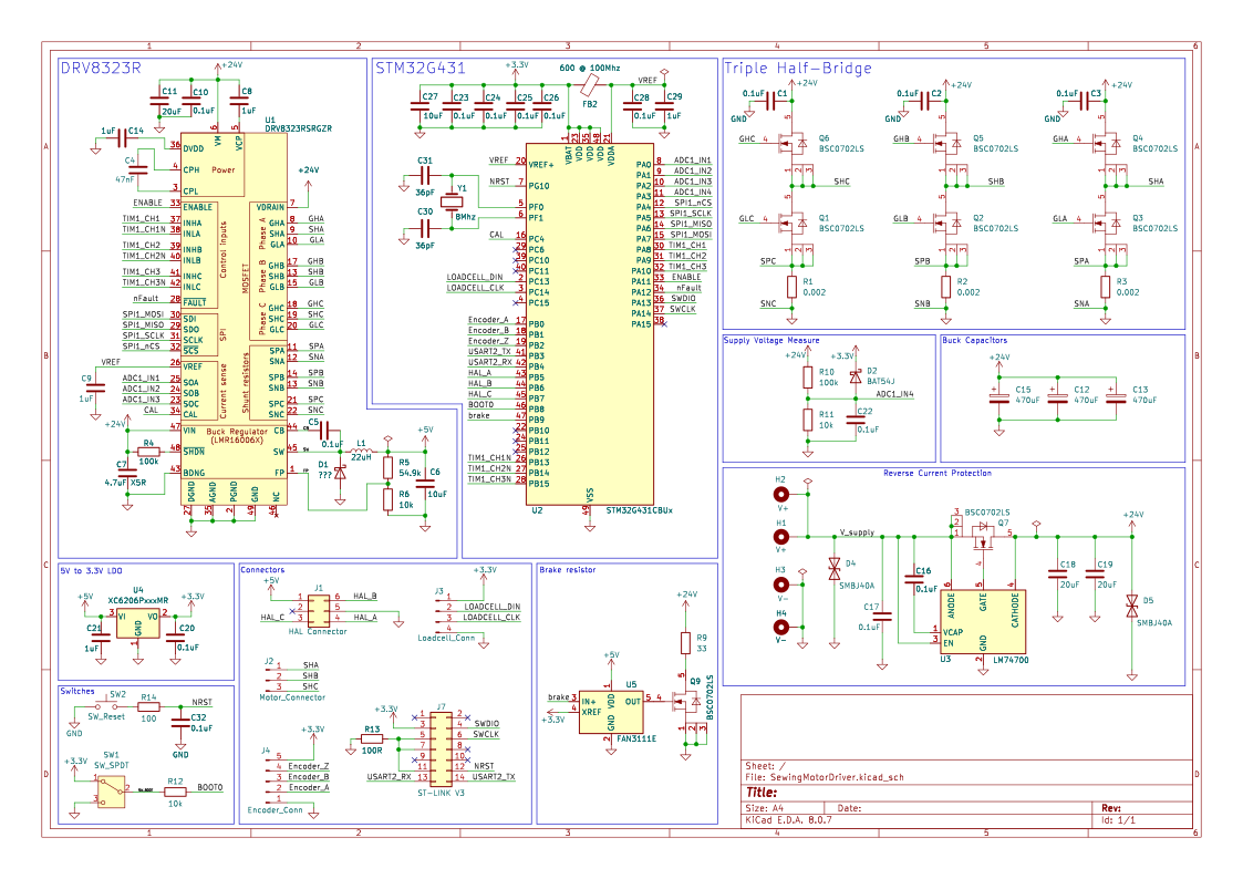
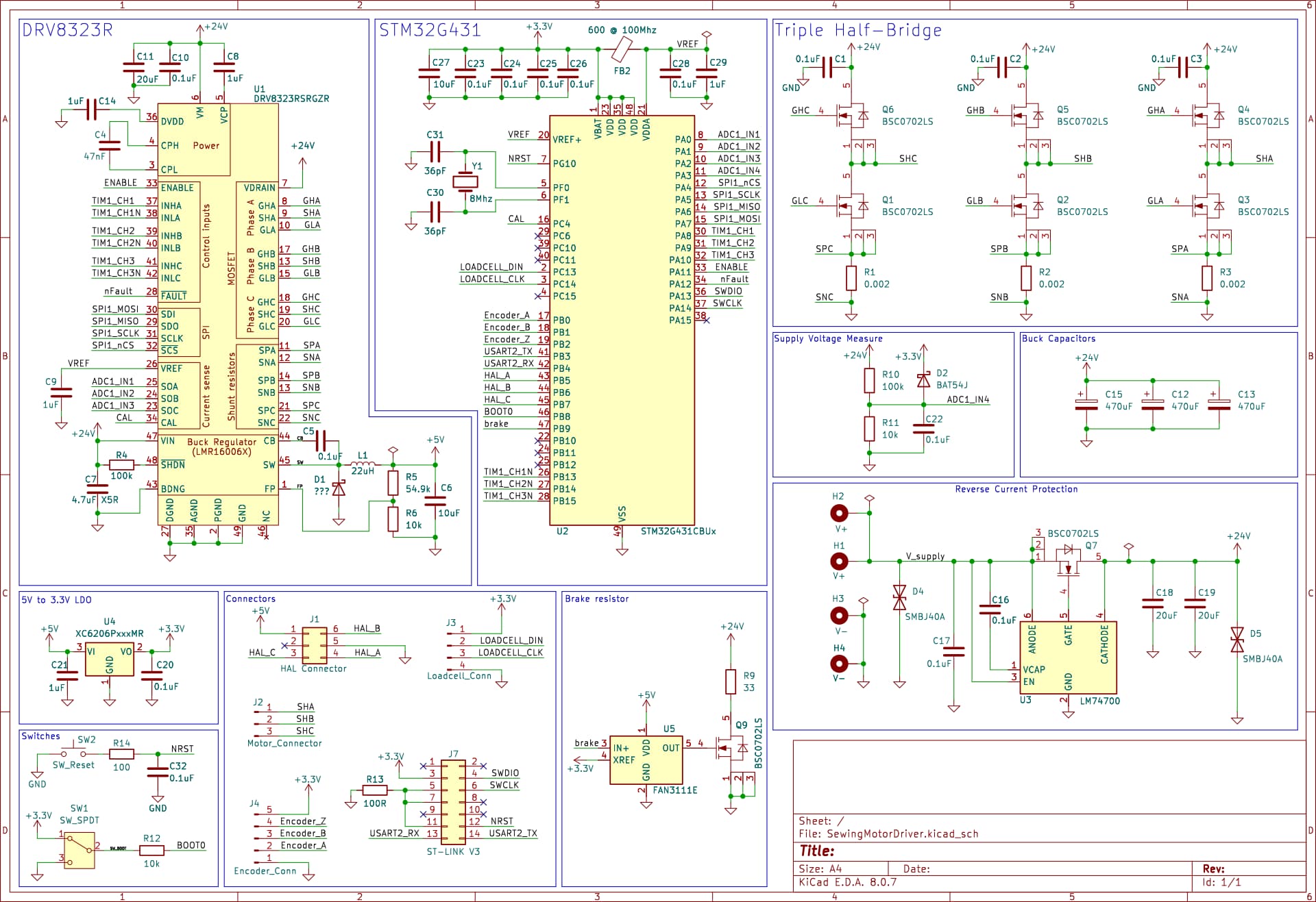
After a long time, I finally found time for the project again. I have now started to draw a simple circuit diagram for the driver board.
The basic structure of the circuit diagram is as follows:
The motor windings are controlled via three half bridges.
The half bridges are controlled via a DRV8323.
The control algorithm is executed by a Stm32G431.
I found the simple solution for securing the power supply using TSV diodes to be inadequate. Apparently, TVS diodes cannot be connected in parallel to distribute the reverse current evenly.
To secure the power supply, I now use the “ideal diode regulator” LM74700.
I have also add a braking resistor that can be switched via a separate NMOS.
I would be very happy to receive feedback on the circuit diagram
I’m looking for help picking components for my sewing machine motor project. I’m novice when it comes to electronics and motors, but I have backing programming. I read most of the posts on this thread and learned a lot.
So the motor is coming for an old domestic sewing machine Necchi Bu Nora. All metal and sturdy components. I don’t need any crazy torque or speed, but step up from the old motor would be nice.
I have thought about getting 57BLF03 motor and DRV8302 driver. Any thoughts? All the help and recommendations are appreciated!
Sorry - I have not been in this forum for some time, and therefore I just now have seen this new post from NicoMayer.
I have looked the diagram, and I am not sure, that I can be of much help. But I learned a bit regarding the impresive driver circuit, DRV8323R.
I should like to see some possibility for some extra input/outputs for needle stop. It will typically require two digital inputs for two digital hall sensors and an input to manually switch between the typical four modes. If you like to have an indication of the needle stop mode, you can do it with two outputs for LEDs. In this video I show one way I did needle stop:
I see the brake resistor of 33 ohm with a circuit and the Reverse Current Protection circuit. I am not quite sure, what the Reverse Current Protection is for - is it to to limit over voltage on the 24 V power supply due to reverse energy from motor and machine? I hope you can explain a bit here.
In my case with the DC motor I used a 6.8 ohm resistor with a circuit as explained above. But I might have prefered about 3.3 ohm when breaking from max speed in my case.
It seems that you plan to use a HX711 AD-converter board for the load cell. What is the rated pressure on the load cell, and should it in some way be protected against overload? Are you satisfied by its use for a pedal?
I got a few more remarks to this design. I have seen your other thread regarding questions to the DRV8323R, and I cannot help you with that, but It seems to be a good choice.
Regarding the load cell used for the pedal, I think I should use one with a max load of 20 kg that should withstand 30 kg load without damage. 30 kg might be applied by some accident blow or kick to the pedal. As I wrote previously I use a range zero to max speed with 0.4 to 4 kg force on pedal. For information, I know some older commercial pedals only got about 2 kg force for max speed:
If you plan to use a PCB module with the HX711 AD-converter, then I like you to be aware of the possible limitations:
According to this library, a safe serial reading of the HX711 requires about 55 us: https://github.com/RobTillaart/HX711/blob/master/README.md
It may be OK, but I think it may be a problem for some other fast responses needed for driving the motor. I think you need to use HX711 with the max speed of reading at 80 readings/sec in order to get acceptable responses. Furthermore you will only be using a small range of the max signal range of the HX711. Be aware of possible unacceptable noise on the received signal. Please look above for my recording of a kick to the pedal I use.
I guess, that some analog amplifier on the board with input from the load cell would provide a more safe approach. And you would then need a manual offset adjustment. But I do not have any practical experience with the HX711 - I just made some reading.
One other way is to choose four TVS diodes in serial. They should more safely share the possible transients loads for breaking the motor speed. You got quite a high margin for the max voltage on the DRV8323 and the transistors. It is much easier than having breaking resistance and other considerations. I suggest these: https://www.tme.eu/en/details/smcj6.0a-dc/unidirectional-tvs-smd-diodes/dc-components/smcj6-0a/
Many of the industrial style BLDC motors got hall-element digital outputs for a controller. Some got analog signals analog hall-elements sensors. But I am not sure that the normal FOC software make use of these signals, when you already got some encoder on the shaft. You may like to use them, but you may also like to have extra input/output pins in reserve.
I make use of an extra output pin for a LED signaling some error modes.
I think this is a prototype PCB, and therefore you will like to be able to access all extra possible input/output pins to the controller by some connectors. Don’t expect to get everything right with the first PCB. The extra pins can be used for extra external circuits in the development process.
Do you have a specific encoder for the motor in mind?
I have to correct myself here. The upper needle stop position would be close to max position of the take-up lever, that finish the stitch forming. You will typically chose a position with the needle coming downwards and the needle point is just above the presser foot in upper position, so the needle point do not catch the fabric, when you like to remove it.
I only found Needlestop really necessary in mass production. For home use or as a tailor, I find good speed control with the pedal much more important.
Fun fact: My mother worked as a tailor in a factory. The industrial sewing machines back then had clutch motors. During her training, she had to learn to operate the sewing machine completely without a handwheel.
Yes exactly, the reserve current protection protects the power supply unit from overvoltage.
Mh There is no overload protection yet. Overloading is not a problem for the electronics. The Loadcell only generates very low voltages. These are amplified internally in the ADC. In the event of an overload, the ADC reaches its maximum value at some point. Nothing more happens (at least that’s what I think)
I don’t know when the load cell is mechanically overloaded. Under load, the load cell bends and the strain gauge changes its resistance. If the load is too high, the strain gauge will be damaged at some point. I do not know when this is the case.
So far I am very satisfied with the pedal. You can use it to control the motor very precisely and directly.
I currently use a 5kg load cell. The old motor on my pfaff 138 reached its maximum speed at around 40nm.
So that fits well with your diagram.
However, the load cell does have one disadvantage. Each load cell has a different voltage curve. It must therefore be calibrated. The voltage curve is linear. I have therefore measured two points on the voltage curve using two weights. I then used this to calculate the conversion formula.
I use this library:
How long it takes to read out a sample depends on the clock frequency generated. Most HX711 libraries simply toggle a GPIO pin to generate the clock signal. This means that the read process takes around 10us to 20us.
If the microcontroller is too fast, an additional delay must be inserted. The 55us from your library refers to this additional delay.
An amplifier is already built into the HX711. An external amplifier probably makes less sense.
TVS diodes in series should work. In the end I decided to use the external Brakeresistor. I hope that this will give me more precise control of the braking effect.
I use an MT6701 as the encoder. There are pictures of it further up in the thread.
I agree, that good speed control is most important, and I guess that the need for needle stop can be a reaction to the already bad speed control. Yes, years back with less developed electronics, you needed to work with the possible solutions for control. And tailors as your mother have been told: “Practice makes perfect”. When servo motors for sewing machines came into the industry, it was a significant improvement. But the culture of “Practice makes perfect” still remains today. It actually prevents further development into even better solutions with speed control in this industry and on the market place. When I work with sewing machines, I think it is a pleasure to have the much better speed control, that is not that difficult to achieve with modern electronics. I guess that when the bigger garment factories in India and China finds out, that they may be able to increase their production with about 5% with better speed control, I guess something will happen.
Yes. Perhaps you still got the values within the dynamic range of your electronics, and then you may do the zero-point adjustment as a start up routine, and then assume or demand, that the presser foot is not pressed when you power-on the machine.
I look forward to hear from you, when you start to get experience with this new drive.
How many magnetic poles do a typical skateboard BLDC motor have?
Previously in this thread, it was established that some of the skateboard BLDC motors may be a good choice for sewing machines. I tried to look on specifications for some of them, but I could not find data on how many magnetic poles, that they typically got. They are normally out runner motors. Can you help me here?
(EDIT: these motors got 14 poles and 7 pole pairs!)
If you use a 14 pole motor at an about max speed of 6000 rpm, the base electric frequency should be 1400 Hz. (EDIT correct is 700 Hz). If this frequency cause a significant audio response from the motor, then it may be a somewhat annoying noise. Do such BLDC motors make annoying noise here?
I guess, that at high speeds, a sewing machine makes a lot of noice anyway, so perpaps it do not matter that much. @NicoMayer previously commented on the annoying audio noise from the timing belt shown in my video above. This noise is significant at sewing machines speeds of 250-500 stitches/minute. This speed range is often used, and here you would like the drive to be more silent. At this speed the electrical base frequency with a BLDC motor would be about 175 - 350 Hz, and such a noise would not be that annoying.
I got a new question, because I just learned about the terms, 3PWM and 6PWM. Can 3PWM be used with a sewing machine?
You like to be able to move the machine by hand on the flywheel. If the motor have the leads given a short circuit when stopped, I assume it would be difficult to move the motor freely. But I think you should be able to enter a zero torque control mode with SimpleFOC, and then you should be able to move the motor anyway. Am I right?
Here I link to the a specific time in my previous video using a BDC motor with a Pfaff 230, and you see how the controller here shifts from high-Z mode to a speed control mode: https://youtu.be/w9AfNjH3q4Y&t=27