Motor drive for sewing machines

This is my first post here - thank you for letting me in your community.

As a hobby, I am working on designing a small motor drive with a brushed DC motor for a few sewing machines. Sewing machines are typically driven by an electrical motor, and the speed is controlled by a foot pedal.

I find the possibilities with the new designs with BLDC motors and FOC interesting, and like to find out what the possibilities might be. I think I got a good understanding of motors in general and the physics involved. But I got a lot of questions, that I like to ask about speed range and short term torque and similar. Is it OK to ask about that here?

This is a video of an industrial sewing machine, that use a BLDC motor drive, that is typical for use on industrial sewing machines on the market today:
https://youtu.be/i552XIOQFDY

You see that the motor jump starts to a rather high lowest speed of about 60 stitches/min. In my opinion, this is not desirable. Normally sewing machines can be worse than you see here. But you do not see that full speed range and small steps. These kind of drives do use BLDC motors, but I think the software is made 20 years ago or more. Typically you will see a lowest speed of 100-500 rpm and a max speed of 4000-6000 rpm. The motor will then drive the sewing machine by a belt, with a gearing in range 1:1 up to 1:8. Max input power to drive is typically 550 W.

Then look at this video with a DIY smaller motor drive on a vintage household sewing machine, and a lot more quality information is provided:
https://youtu.be/uTB8DnyYAlA

You see very low speed. No jump start. Large range of speed. Possible small movements by kick to pedal. Good speed control for load variations at very low speed. This is quality on another level. But I think it might be possible to do something even better. The max speed is too little as presented in this video.

Actually most sewing machine users are used to very bad speed control of their sewing machines, and they have not realized, that it could be made much better.

I would like to provide more information and ask several questions. But I guess this will be a start.
2 Likes

So what was your question? If it is possible with SFOC, yes.

I think it’s a cool project, for sure. The tricky part is finding the right motor 500w is not much.

I will advise against using Flipsky type hoverboard motors, they consume to much power. Perhaps one with a wide diameter, wound for lower amps, but still with a decent KV rating. You probably need to use at least 48v. Of course there is a lot of wiggle room between 1:1 to 1:8

1 Like

Thank you for the comment. I shall try to state some specifications for a drive, and then I shall start to ask some questions.

Please disregard the typical specifications for an industrial sewing motor drive, that I placed above. Look below instead:

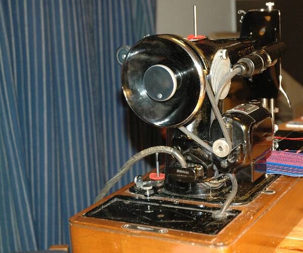
This is what a typical motor with belt on a vintage sewing machine looks like. The typical V-belt gearing will be about 1:3.5:

It will be easiest to be able to mount a motor in a similar way. The sewing machine often have a cover, so you can transport it or store it away, when you do not use it. Therefore you do not like the motor with drive to be too big. But if necessary, there is other solutions to make the gearing different, it just takes more effort. With the brushed DC motor I soon will get, I shall use a gearing of 1:10 with a timing belt. Some new machines also got solutions, with a motor connected directly to the main shaft of the sewing machine.

I will now make some speed and torque specifications, and they are for the main flywheel shaft of the sewing machine. With a gearing to motor you will have to convert accordingly for motor torque and speed.

High speed:
Max speed: 2000 rpm
Max shaft mechanical power: 140 W
Shaft torque is then: 0.7 Nm

Low speed:
Lowest speed shall be below: 8 rpm
Max mean torque at low speed: 1.2 Nm (25 % duty cycle)
Short term torque at low speed: 3.5 Nm

At low speed, the needed torque vary a lot in the sewing cycle. Therefore a fast speed control is needed there. Speed control is no problem at high speeds. This is what a hard point in the sewing cycle looks like:

The motor is expected to heat up, when it needs to deliver the short term torque, but the torque is only required within a very little part of the time. The 1.2 Nm mean torque given above is not supposed to be a torque needed 100% of time, because most of the time you do something else than have the machine sew. I think that 25 % of time with 1.2 Nm would be normal for thermal considerations. But some temperatur evaluation or measurement of temperature might also be in order.

You need to provide a controlable speed in the full speed range of 8 rpm to 2000 rpm. When you start sewing, it is important that the motor do not jump start. It is actually prefered to have a little audio indication before the motor starts to turn, because then you are preparred. However the general audio noise from the motor should be nice and not annoying. It is good when the audio indicate something about torque and speed, because it is actually a good and fast feed back to the user of the sewing machine. But this is no rquirement.

I prefer to use a 24 VDC supply for power, but it is no requirement.

Questions:

  1. I consider the right technical term for the motors in question is like this:
    14-pole synchronious motor with permanent magnets. But the normal term used are BLDC motors. Am I right?
  2. I have seen two kinds of motors. One type for drones with about 14 poles and another for RC cars that got about 4 poles. Am I right?
  3. I have seen examples of drives that do not use an encoder, but can control a low speed without secondary feedback. The drive can measure speed by frequency injection or other means. Just controlling like a stepper motor may also be possible. Do this kind of sensorless systems got drawbacks?
  4. Assume, that you got a 14-pole motor that runs at 15.000 rpm. Then you can calculate the base frequency of the motor windings to be 1750 Hz. You will typically switch configuration of the 3 phase bridge 6 times each cycle, and it means 10.5 kHz. It will require further switching of transistors to to place the current vector correct, and I have seen 6 transitions to do that, so it makes 63 kHz. Is it normal in this situation, that you need to switch the transistors that fast? I do also think, that it might be problematic for the microcontroller to set the transistors that fast withou some dedicated hardware. Are this example right and what might be wrong.
1 Like

This seems like a great project! I am also working on a motorized application for textiles, but instead for knitting machines instead of sewing machine :smiley:

There are also gimbal, which have higher pole pairs, and higher torque at lower currents. The top speed is lower but you have more position control.

I would not do sensorless unless you really have a good reason why, if you have the space for a sensor, I’d really recommend to do that. There has been a lot of improvement on sensorless for simplefoc lately but it does require careful analog design to make the most of it.

Yes and no, the FETs are switched in pairs, so it’s not x6 like you calculated, but you have the idea right, for 6-step. If you want to do FOC, the current forms a continuous sine wave rather than discrete steps. You do indeed need dedicated hardware. The speed is not a problem for modern microcontrollers (stay away from ATmega like older Uno, etc). There is quite a lot of discussion on this board about motor driver boards, you can read about them here, try to find some online or design your own.

I would recommend trying with a stepper motor, something like NEMA23 could provide the amount of torque that you need at low speeds. The only issue will be that your max velocity will be limited due to the large BEMF from the very very low kV rating of steppers.

1 Like

Thanks. Yes, I have seen some remarkable solutions with sensor less control on YouTube such as this:
https://www.youtube.com/watch?v=vJXnunhm1c4

I have looked for encoders, with about 1000 lines, and they are rather expensive. But perhaps other encoders is preferable. You will also be a clumsy design, if you do not have shafts on both ends of the motor, so you can place an encoder in one end and the pulley in the other end. It can limit the amount of motors available.

One other important requirement is low cost for these drives.

Yes, I know that the low speeds will be in order with a stepper motor. This have been tried as you can see here:
https://www.youtube.com/watch?v=IsPLIEXFASw
But I cannot accept the very limited maximum speed, that you get from a stepper motor. I think most of the stepper motors with about 200 steps each revolution got a max speed at about 1000 rpm. A main reason to try an alternative drive solution is to get a very wide speed range - it is not just making something work.

Have you seen any magnetic encoders? They don’t require exposed shaft. Some motors can come with magnet, others you can glue/epoxy on. It is non contact, high bandwidth, adjustable resolution and very very cheap.

Well, with gearing, you can increase the speed at cost of torque, and there is plenty of torque to give up with stepper motor. I think the solution in that video is somewhat naive as you are substantially gearing down the motor (small drive with belt to much larger wheel, like using granny gear on bicycle). It should be the opposite for higher speeds. With stepper motor and supply voltage of 24V, I was able to get about 220 rad/s which is around 2000rpm.

In my experience up to now on some brushed DC motors, you need a control loop regarding speed, that has a frequency above or equal to about 1 kHz. With a digital encoder, it can become a problem at low speeds. But I guess that you think of some hall sensors, with an analog output. In this way you should be able to get measurement a faster and cheaper way.

The encoder requirement is a bit different here, because you might not need to have position information, unless you need it for correct placement of current vector with FOC. I have studied alternative encoder solutions to measure speed using small brushed DC motors (tacho generator), and it is a very cheep solution, but it require access to a shaft on motor. Another similar possibility is to use another three phase BLDC motor and measure the EMF from it on two phases.

Thanks, I will look into the possibility with some stepper motor. However, this forum should know a lot about the usual BLDC motor drives, so I hope for some help here to suggest a motor and perhaps an ESC that might be useful.

No, no, not hall sensors, magnetic encoders, like AS5048, MT6701, etc. They work fine from low speed to several krpm.
Yes, you need position info of some sort to do FOC, either encoder, absolute position sensor, hall sensors, or sensorless (which still has sensors, but it is current sensors using injected signals). Without any of those it’s not possible to do “real” FOC. SimpleFOC does not have support for BEMF sensing yet.

I have tried to find out what a gimbal is, and it was not that easy. I think these two links explain best:
https://www.sierramotion.com/blog/gimbal-motor/
The link above explains, that a gimbal is a two axis optical camera system. It is typically used to track something to keep the same object in camera sight. They typically use direct coupled large diameter motors with many poles to set the direction angle of the camera. So these motors got many poles and are not optimized for power but to provide a position and with no cogging moment.

Then this link from this website:
https://docs.simplefoc.com/bldc_motors

It states that the motor typically got a resistance above 10 ohm and got more poles than normal BLDC motors.

With 10 ohm resistance of motor coils, it can be calculated, that the upper limit for shaft power possible will be 14 W using 24 VDC and 58 W using 48 VDC. So it is significantly below what is required. So I guess that gimbal motors is outside the scope to be used.

You could most likely get a custom wound motor from one of the hoverboard-motor fab sites. That would interest me a lot to know if and how much or why not. The saying goes, that hand wound stators are tighter, but maybe that’s just some urban myth. Let’s say your motor can handle 10amps peak for some duration, without overheating, that’s 480w @48v

Edit: maybe you can fit a e-bike hub motor ?

Edit x2 : Don’t know if you have seen this, but last year I did some work on this modular design. Perhaps we can colab on what you need. I also intent to use it for the barrel and the induction heating. I suspect we will need some serious power to spin the helix in the community-cooker thing. You could also dive into the whole thing your selv, it is a very delightful process w. KiCad :smiley:

Thanks. OK, then position is needed for FOC. But is the position also needed at higher rpm? At higher rpm you can use calculated power to motor (derived from motor current measurement) and in this way correct the angle for frequency controller of applied current angle to motor.

I looked up these specified magnetic encoders, and they are based on hall sensors and consist of two or three internal hall sensors to measure a magnetic field vector. But these sensors got a I2C interface and their own ADC. I previously looked at some similar sensors from Infenion, and they got an upper frequency limit for measurements at about 8 kHz. Therefore I guess, that some analog hall sensor would be better, and then use the microcontrollers internal ADC, because then you are able to measure faster and with more accurate timing.

BEMF is Back ElectroMagnetic Force - right?

Look up hardware encoder interface. It basically is a dedicated timer counting the ABZ pulses (encoder signal). With these signals you can also measure/count velocity using the MCU base-frequency as time factor. :zap:

Now you think of a digital encoder with many lines each rotation - right?

Yes many lines of code

From our own website with link above, some motors are proposed and one with a price $20. The link to buy this motor did not work anymore, but I used google to find this motor elsewhere, and found it on these links:
https://vi.aliexpress.com/item/32740690041.html?gatewayAdapt=glo2vnm#nav-specification
https://www.amazon.com/SURPASS-Performance-Brushless-Airplane-Fixed-wing/dp/B01MAUFDHW
https://www.banggood.com/da/SURPASS-HOBBY-C28-Series-V2-C2834-750KV-or-880KV-or-1120KV-Outrunner-Brushless-Motor-for-RC-Airplane-p-1993305.html

As a start I tried to find some data on this motor, and I hope you can help me translate them to some useable data not only for drones or propellers. The coppied data is like this:
Specifications:
Brand name: SURPASS
Item No.: C2216-10
KV(RPM/Volt): 880KV
Watt: 340W
Voltage range: 7-18V
Max amps: 22A
IO: 0.8A
Resistance: 0.108
Motor size: Ø28 * 34mm
Staror size: 2216
Recommended propeller: 11 * 8.5 / 10 * 7 / 12 * 6
Connector: 3.5mm golden banana connector
Weight: 67g

What do the 340 W refer to?
Is it max input electrical power to motor?
Is it max input electrical power to ESC?
Can this small motor withstand that power a long time with good cooling?
What is the expected shaft mechanical power in this situation?

A resistance of 0.108 is specified and 22 Amps max. I guess that is is 0.108 ohm. Then the power loss from the resistance should be about 52 W.
Is this 0.108 ohm at 25 C temperature of the windings or some other temperature?

The max no load speed should be 880 x 18 V = 15840 rpm.
Am I right?

What kind of torque do this motor produce at 22 Amp current?

1 Like

Many questions :slight_smile: and a cool project!

For the power levels and range of speeds you need, it will be a little bit of a search to find the ideal motor :slight_smile: But there is also an argument to be made for empiricism: I think a sewing machine won’t be sooo hard to make work, so why not just get some of the cheaper options, hook them up and see how you like the performance?

You might want to look at stepper motors too. You can drive them in FOC mode also, and they are not expensive and widely used in 3-axis machines like 3D printers, which go pretty fast these days… for a stationary application like the sewing machine the high weight of the stepper isn’t really a problem.

Your guess is as good as anyones. Often, even if you contact the manufacturer you won’t get a satisfactory answer. Motors with good data sheets and full information are available from companies like Mason, Faulhaber or Portescap… here you will find a motor you like, and also with different options for built-in encoders. But these come at totally different price-points, literally many times the cost.

One class of motors you might look at is drives for pick and place machines, and similar industrial automation jobs. Pick and place is one area where you need to go both very fast and very slow, with very fine control, but of course these machines don’t need much torque.
Still, brushless servos in NEMA23 or NEMA34 size or similar might be a source of motors that work.

Even with good cooling, I would have doubts. But certainly it would need forced air cooling.

Again, you’ll only ever get such information empirically, or from top-brand manufacturers which might supply such curves.

From better companies you’ll get curves. For the drone motors you sometimes get tables listing lift/torque for different currents and propeller models… :-/

Let us know how your search goes, and don’t hesitate to post more questions :slight_smile:

Thank you for your answers.

I guess, that some people in this group might have experimental data for this motor, because it is one of five motors suggested by this website, and they are characterized as high-performance motors. But I do know, that it is not an expensive motor from one of the high end motor manufacturers.

Yes, I have noticed the lift data from propellers. But they are hard to evaluate unless you know detailed information about the propellers torque speed lift characteristics.

One way to calculate torque would be to assume, that all remaining power, that do not cause heat loss in windings will be shaft power. A calculation based on this assumption would be:
Resistance voltage loss in windings will be 22 x 0.108 ohm = 2.4 V.
The EMF from motor will be 18 - 2.4 V = 15.6 V
The shaft power will be 15.6 V x 22 A = 340 W
The motor speed at max power will be 15.6 x 880 = 13.700 rpm = 1440 rad/s
Then torque at 22 A would be 340 / 1440 = 0.24 Nm.
This torque will be a bit optimistic value.

If I assume, that you should not at any time drive the motor at higher currents than 22 A, then this motor do not meet the requirements set out further up, because then you need a gearing of 15:1, and then max speed will become only about 1000 stitches/minute.

I got plenty questions :grinning:

I know that you might damage the permanent magnets, if you provide to much current to such motors. This damage current - is it well above the max current specified or should you newer provide more current (short term) than this specified max current?

I have noticed, that two ways of driving the transistors:

  1. three half bridges is always active and two terminals to motor got same voltage and the last terminal got the same or some other voltage.
  2. Only two half bridges are active at same time, and one of the three terminals got a “floating” voltage.

In principle you could use both methods and get 12 transitions each period of the sine wave current applied to a terminal of the motor. But I have not seen that proposed or used. Why can that be?

It’s not the current which damages the magnets, but the heat - so the problem is sustained high currents, which generate a lot of heat in the windings. The solution is either cooling or not to use continuous high currents.

Again, better manufacturers might give you a rating for the continuous current the motor can handle, but for drone motors I would assume that the numbers given are
a) somewhat aspirational in the first place
b) represent some theoretical max value that isn’t useful in practice

The switching of the transistors does not have to be related to the field oriented control.
In 6-step or simple trapezoidal commutation you’re driving the commutation with the “minimum waveform” so to speak, and using only the supply voltage or the off states. This results in the overlapping square waves with distinct steps, and as you say, represents the minimum number of FET switching events, or transitions, that you can have. But the resulting current waveforms are not very smooth (sinusoidal).
This type of control is better when you want to turn the motor very fast.

SimpleFOC runs the phases in PWM mode, switching the FETs of the inverter at many times the frequency of the commutation waveform. The PWM duty cycles are also updated several times faster than the 6-step pattern transitions, so the result is much more like a sine-wave, changing smoothly over time.

So in terms of the FET switching you can expect not 12 transitions per electrical revolution, but maybe 60+ PWM duty cycles per electrical revolution, and many more if you’re only going slowly.
And in terms of the commutation pattern, it is no longer “square shaped” with 12 transitions, but rather a smooth sine wave…

Thank you for your answers.

I am sure, that there is a current limit in order to not demagnetizing parts of the magnets, but it may very well be that high, that it will have no practical importance for the normal kind of BLDC motors used for drones and similar. In worst case you will have to apply the current in a way, that will force the magnetic field in opposite direction than what the permanent magnet supply.

Brushed DC motors with permanent magnets are normally designed so the magnets will not be damaged by the stall current. If you got a DC motor specified for max 24 V DC, you will get the stall current when you apply the 24 V and block the rotor. However, if you have the motor running full speed, and put a reverse voltage of 24 V on the motor, many such motors will be damaged. Then you got the EMF from motor and the supply of 24V making just below 48 V driving voltage trough the resistance of the windings. In this case, the short term current can be sufficiently high, that parts of the permanent magnets will be demagnetized. The stall current of a brushed DC motor is normally about 6 times higher than the thermal nominal full speed current. So a short time current of about 12 times the nominal current will damage such a motor, and it will be before any thermal problem becomes a problem.

I have looked for some information on these drone motors, and it seems quite common, that they get damaged by heat, and it fits your description. But I guess that it is normally the insulation of the cobber windings, that is damaged.

Have temperature classifications on the enameled cobber wire used been an issue for selecting drone motors?
This is a link explaining a bit about that:
https://www.linkedin.com/pulse/13-understanding-insulation-class-enameled-8etge
The temperature rating given is for quite long time use, so the insulation can withstand higher temperatures short term, but there is limits to that. But no doubt, that a class B cobber wire is cheaper than a class H wire. There is an old saying, that a 7 degrees C increase in motor temperature will cause half the life time of an electrical motor.

I am well aware, that you use higher PWM frequency than the electrical period frequency of the motor speed. The two situations I mention refer to any split time situation. But you might need to use situation 1 all the time for FOC in order to place the current vector accurately. With situation 2 you force a specific direction of the current vector unless current in free wheeling diodes are involved.

I guess, that some PWM hardware timers of the microcontroller are somewhat involved in how the six switches are controlled. Do you know some good sources of information about how this hardware is designed for FOC?

I think an e-bike hub motor is much too slow, and gearing to drive a sewing machine at 2000 rpm seems not right. The normal max speed of an e-bike hub motor is about 150 rpm.