Motor drive for sewing machines

I have now parameterized the PID controllers and carried out the first tests.
The results don’t look good:

Target speed = 100 rad/s

Target speed = 10 rad/s


The motor speed oscillates strongly. At low speeds the motor makes a jerky motion.
I suspect that the cogging torque is causing the problem.

Does anyone have an idea how I can fix the problem? I currently have two ideas:

  1. Attach an external encoder to the motor
  2. Organize a motor with low cogging torque.

The max speed is 540 stitches/minut (info is provided in video). The gearing to motor is about 1:20 and make use of a small speed reducer. I already know, that a brushed DC motor will be able to perform better than seen here with a wider speed range, but the cost of components are larger as well.

I agree. :slightly_smiling_face: Some more work on that is needed.

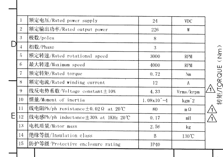
It is a very good question. I tried to have the motor run slow with a current of 13 Amp for 5 minutes, and immediately after that I put in a K-type thermo coupler into the windings to get an idea of the temperature, and it reached 95 C. I think the mean cobber resistance at 25 C is 0.12 ohm, so the resistive loses at 95 C would be about 26 W. It is my plan to estimate motor temperature in software, by use of the measured motor current.

I use an H-bridge called IBT_2, and it got serious problems due to switching losses, that becomes far bigger than the losses due to on resistance of the power mosfets. Therefore, some of the programable ESCs on market may very well perform better if they are used with a brushed DC motor. Therefore some ESC with a number of extra input/output pins could be an advantage.

Thank you for this link, that got a lot of information. It will take some time to read and understand. But from a short reading it looks interesting.

I have been looking for data, that might give an idea of how responsive such drives are. In the mean time I think I found it in two other links:
This video show a measured step response with a transition time of about 100 ms, and it is based on measurement on sound:
https://www.youtube.com/watch?v=XjhY2tyhYZ8

This other video is only 4 weeks old, and compare the step response on five different ESCs for drones performed on the same motor and propeller:

To me all five ESCs perform almost equally fast, and differences are minor. The time for the speed change 10% to 50% throttle is about 50 ms. I think it very fast, and it show me that there is nothing special about these kind of motors and drives, that makes them less responsive than a brushed DC motor. Perhaps brushed coreless DC motors are faster, but it is another matter, and faster controls than shown here is not needed at all for sewing machines.

According to this video, the use of FOC in ESCs for drones is new, and one of the five ESCs tested are this new ESC on market. It might perform a bit better, but no significant change, when I look the test data. Without knowing much about this, I should think that breaking of the motor could be done faster, if you want to make the ESC do this more actively. It seems that short circuit of terminals are used as the way of breaking. There is no drought good reasons for that.

I can answer this, no, they don’t have the same parameters, the parameters vary with the D and Q axis inductance respectively. In my opinion, the best way to tune these controllers is to use pole placement, calculated with the motor parameters, something along the lines of this:

    PID_current_d.P = Ld*current_bandwidth*_2PI;
    PID_current_d.I = PID_current_d.P*(phase_resistance/2)/(Ld);
    PID_current_q.D = 0;
    PID_current_d.output_ramp = 0;

    PID_current_q.P = Lq*current_bandwidth*_2PI;
    PID_current_q.I = PID_current_q.P*(phase_resistance/2)/(Lq);
    PID_current_q.D = 0;
    PID_current_q.output_ramp = 0;

Using that same method with a different project, I recorded this chart. The motor/controls displayed here implement a profiled move of one revolution, anticogging, 20kHz PWM/40kHz control loop, and 2kHz current control bandwidth tuned via pole placement with a 4215 sized 650kv drone motor, with a relatively low resolution 12bit encoder. The motor was unloaded and the motion profile/controller was tuned for that load case.

and here’s the before/after anticogging for velocity error at a constant q axis torque setpoint, no velocity feedback.

I should like to know what it means? It is a two axis hall element on shaft with a 12 bit AD converter?

In your last plot on speed changes due to cogging moment - can you provide some idea on the units on the two axes?

It seems that cogging moment is an issue at low speeds for these kind of BLDC motors as it is as well on conventional brushed DC motors. I tried to measure the cogging torque of the motor in my set-up, and the measured torque is the added torque of cogging moment and static torque due to the brushed, and it was about 0.65 N x 29.5 mm = 19 mNm.

In my case with a brushed DC motor, the speed controller have to work fast and hard to limit the variations in speed. In this case the motor speed is 120 rpm and you see the time of about 1.1 revolution. The rotor got 5 poles, and therefore you got a ripple torque and current with a frequency of 10 times the rotation frequency. In diagram you see how the three parts of the speed PID controller contribute to the control of reference signal for current. The speed loop runs at 2 kHz and therefore, the speed loop had repeated 8 times for each dot you see in the plot.

12bits refers to the number of counts per revolution, this encoder is an MA730 magnetic encoder that is working in ABZ mode and has 2^12 counts per rev.

Units are rad/sec for the Y axis, and seconds for the X axis. So around 100rpm. The high frequency variation in the after plot is largely due to the quantization of the encoder along with the very high sampling frequency of that system (40kHz). Qualitatively, the cogging torque on this motor is BAD, it’s the worst of any of the motors I have here. After, it’s almost zero, except when you feel a glitch due to the low encoder resolution and the high slope of torque per angle. To be clear, this result is without a speed control loop running, it’s just putting in the smallest constant current that will keep the motor spinning reliably.

Thanks. I looked up the data sheet, and I think it is this:
https://www.monolithicpower.com/en/documentview/productdocument/index/version/2/document_type/Datasheet/lang/en/sku/MA730GQ-Z/document_id/3563
As far as I can see, the chip is based on two hall elements to measure a two dimensional field vector, and some computing of the analog signals from them to produce the ABZ signals.

Just to be sure what is going on. Here is my guess: You sample the A and B signal at a rate of 40 kHz (25 us). Then you count how many readings is done until you gets a shift in one of the signals. It is such count value, that determine the speed. I know some Arduino users use interrupt routines triggered by changes in AB signal and then they measure the time passed between every interrupt of same kind. It might also be some more direct digital hardware, that measure the time between transitions with a fast counter. I guess more methods can be used.

Not quite, this project uses a teensy 4.1 and runs FOC for the rising and falling edges of the pwm cycle. The encoder is handled using hardware features of the MCU, so it’s nothing is actually polling the encoder lines, the hardware updates the count register in response to the inputs changing without cpu intervention. This code uses the difference between samples to calculate the velocity, though it’s almost certainly possible to use a timer to measure the elapsed time between edges and use that as a better estimate of velocity.

Thanks. The reason why I am interested in this detail is, that details about the encoder is important with a wide operating speed range, that I wish for a sewing machine drive.

I am still not sure, that I can make sense of this. Now I try to make a point with calculations:

The speed of motor is about 10.5 rad/sek or 1.67 Hz rotation frequency. You got a resolution of about 0.95 rad/sek or 0.15 Hz.

With 2^12 transitions each rotation, the counter counts one up with a frequency of 6840 Hz. It might also be 4 times higher if each transition of the AB counts - then it gets about 27 kHz. If you sample the counters value each 25 us, then the counter will sometimes have counted 1 and sometimes 0. So it makes no valid resolution of speed for each 40 kHz sampling.

So I still miss something. Perhaps the rad/sek is the electrical radians of the electrical cycle and not the shaft cycle?

Look at how long it takes the motor to do the profiled 1 revolution, this motor also will spin ~20krpm when not limited to such short moves.

The control loop frequency is fixed to the PWM frequency, so there are cases where it’s faster than necessary, but it’s also infeasible and unnecessary to change the control loop frequency based on current operating point.

Yes, typically you use the sensors in quadrature mode for 4x resolution.
The sensors have internal processing and a limited bandwidth. As the speed increases the accuracy decreases. Their Datasheets contain more information on it.
The ABZ type interfaces are best used with dedicated hardware, which we support for most STM32 MCUs. In this case the counting bandwidth is limited by the timer clock frequency and is very many times higher than needed.
If using interrupts (which we also support) to count the pulses bandwidth depends strongly on processing capacity for the interrupts and is much lower than with dedicated encoder inputs.

Many people use encoders/sensors with SPI interfaces. In this case the value read is digital and the interface bandwidth determined by polling frequency and lag.

No the encoders (unlike hall sensors) are in terms of shaft revolution since they are attached to the motor shaft, or read a magnet attached to the shaft.

Thank you for the clarifications. I try to make sense of this - but still fails.

With the speed of 10.5 rad/sek, you then have the counter counted one up at 27 kHz. In order to get a resolution seen here to be 0.95 rad/sek, you need to see 11 counts before reading. It means, that the rate you sample the counter is 27 kHz/11 = 2.5 kHz. Even though, the speed loop may operate at 40 kHz, you cannot in this way get a valid reading of speed by more than 2.5 kHz.

If a method is used to measure the time between every transition at 27 kHz, then the speed loop will not see a new speed value faster than that. In order to get this resolution of 0.95 rad/sek, then the counter measuring the time between these transitions should have a frequency of about 11 x 27 kHz = 300 kHz. It is a very low internal count frequency, and it makes no sense. The internal counter could easily be about 16 MHz. Such a way to measure time between AB transitions should provide much better resolution, but still no new value more often than at 27 kHz.

With the hardware counter, there is no time needed to sample, the value of the counter is always present in the register, you just read it.

For hardware velocity measurement, it is another counter, chained onto the first one, which is checking a free-running counter value at the time when you see another edge on the encoder lines. If you know the counter frequency then you can easily work out the “real time” between edges, so no calculation is needed, and this is also a register read, so there is no latency other than the value not updating between edges, but there is no way to avoid that here… so in both cases, you can run the control loop as fast as you like, there is no “sample frequency”.

I really think you would gain a lot of knowledge from just getting some development boards and exploring these things yourself, trying to understand the theory of how motor control works down to atomic structures without ever testing things is not the best way to learn about embedded development, I think.

It’s possible that I low pass filtered that data before plotting, I made that a while ago and honestly don’t remember if it was low pass filtered or not. I can say that both traces would be filtered the same way. That method of anticogging uses the derivative of velocity to calculate the cogging torque and consequently build the anti-cogging map. Since the velocity data is recorded all at once and analyzed offline, you can filter the data in a non-causal manner, which prevents the addition of a delay/lag into the data. This means that a low pass filter is safe to use to build an accurate cogging torque map.

Anyhow, this seems like a digression. There are plenty of methods for estimating the velocity of a PMSM, as mentioned you can use a timer to measure the time between edges. You can also use the current sense data and motor parameters to estimate the velocity. If you were really ambitious with the math you could use a data fusion algorithm like a kalman filter to intelligently combine both sources. Additionally, that controller employs several sensorless commutation techniques, which can actually have higher resolution (time and angle) than that encoder, though I didn’t use those to make that plot.

This method of calibration is pretty straightforward, and I’d be happy to share it (it may already be posted publicly, I forget if I updated that repo). It’d be great if someone wanted to port it into sfoc.

I’m with VIP, it seems like you’ve got a really good idea of what motor you might require to run your machine. It seems like it’s probably time to procure a motor and driver and see how reality matches your model.

Thanks for the useful information. What is the current_bandwidth in your calculation?

I have now bought an 80BLD300L2 BLDC motor on Ebay for €50. The cogging force of the motor is significantly lower.
I will try to set the controller parameters for the new BLDC motor using your calculations.

To further improve the speed control at very low speeds, I also ordered an AS5600 board and a magnet.
Does anyone have some tips for this encoder?

Another unresolved problem is the motor mounting. My idea is to design the motor mount as a 3D printed part and print it out with ABS. Does anyone have experience with motor mounts?

Current_bandwidth is the desired bandwidth of the current control loop, in units of Hertz. I’ve been using a value around 300 for small gimbal motors. You should also set the current LPFs to something like 1-1.5kHz (which is entered as 1/(1000*_2PI), btw).

My suggestion for the as5600 is to not use it and to buy something like an as5048 instead, the i2c interface is very slow, even in fast mode, compared to spi. The delay in acquiring angle data caps the performance of the control loop somewhat significantly. If you’re using an stm32, which I’d recommend, then you can also consider the ABZ quadrature type encoders from vendors like cui, or the magnetic encoders like the mt6835 or ma730 that also output the angle in quadrature format.

Thanks for your answer. I have now entered the parameters from the motor data sheet into the calculation:

  constexpr float phase_inductance = 0.17e-3; // 0.17mH
  constexpr float phase_resistance = 80e-3; // 80mOhm
  constexpr float current_bandwidth = 300; // 300 Hertz

  motor.PID_current_q.P = phase_inductance * current_bandwidth * 2*PI; // 0.32044
  motor.PID_current_q.I = motor.PID_current_q.P * (phase_resistance/2)/phase_inductance; // 75.3982
  motor.PID_current_q.D = 0;
  motor.PID_current_q.output_ramp = 0;
  motor.LPF_current_q.Tf = 1/(1500*2*PI);

  motor.PID_current_d.P = phase_inductance * current_bandwidth * 2*PI;
  motor.PID_current_d.I = motor.PID_current_q.P * (phase_resistance/2)/phase_inductance;
  motor.PID_current_d.D = 0;
  motor.PID_current_d.output_ramp = 0;
  motor.LPF_current_d.Tf = 1/(1500*2*PI);

I also tried setting the controller parameters using this tutorial. This gave me similar values to your equation. So the parameters seem pretty plausible

  //current q loop PID 
  motor.PID_current_q.P = 0.31;
  motor.PID_current_q.I = 130;
  motor.PID_current_q.D = 0.0005;
  motor.LPF_current_q.Tf = 0.01;

The speed of I2C also worried me. I hoped that the speed would be enough for the first tries.
I like the idea of VIP with the use of hardware timers. There are also cheap boards with the MT6701 on Ebay. According to the data sheet, the MT6701 also supports ABZ quadrature. I will also order a board like this.

Yes, it is the second method I mention. In this way you measure the time between edges from encoder by a counter. However, in this way you got plenty of resolution of the speed measurement, because you would likely choose a high frequency for this counter. But the test data show poor resolution of speed of only 0.95 rad/sec. That is the reason I cannot find a match.

Yes, it may be necessary. I have got many years of experience real time hardware and software, but you got so many ways things can be done, that it is not always simple to see the method used from test data.

The reason the data I showed has low velocity resolution is because I didn’t try to optimize velocity measurement. For the task at hand that resolution was more than sufficient. The task that used that data (building an anticogging map) used some frequency filtering techniques that reject that high frequency variation.

As you can see in the original graph, the anticogging totally eliminated the low frequency speed variation, which was the goal.

I made a short video with a recording of the motor current to the DC motor while sewing a relative heavy vinyl fabric. The speed controller keeps the speed constant, so the applied torque to the sewing machine is close to proportional to the motor current:

The peak short term torque to the sewing machine is in this case about 2.3 Nm, and it equals 160 N (or 16 kg) down pressure on the needle to penetrate the vinyl. High torque is needed in about 6.5 % of the sewing cycle. The proposed maximum torque I have estimated for the sewing machine is 3.5 Nm or 25 kgF on the needle. However the H-bridge I use (IBT_2) in this set-up cannot manage that high current, and you need to limit the current to 26 Amp, and it equals 2.9 Nm.

In order for others to make a motor drive for a sewing machine, I guess that some actual relevant measurement data can be useful in alternative to nothing at all.

You can find a bit more data about this DC motor drive used in these two videos:
https://youtu.be/w9AfNjH3q4Y
https://youtu.be/Ig69cM_0w7Q

1 Like

Hello, the motor performance looks great. But the noise of the belt is pretty annoying. You are using a toothed belt for the drive. It would therefore make sense to use a toothed belt pulley for the sewing machine. You could perhaps drill some kind of profile into your wooden pulley using a pillar drill:
WoodenPulleyWithProfile

There is also progress on my motor.
There is a hole on the back of my motor that was covered by a sticker. I removed the sticker at this point and attached the MT6701 encoder there:


The motor now runs smoothly even at speeds of less than 10 RPM.
In order to be able to rotate the motor freely when it is at a standstill, I deactivate the motor when it has stopped. However, if I activate and start the motor again immediately after deactivation, the motor starts quite roughly. I have now built a lock into my program code. The motor can only be activated again 500ms after it has been deactivated. Does anyone have experience with a problem like this?

I also noticed that the voltage on my power supply rises to over 30 volts when the motor slows down.
Is there anyone who might have experience with braking large BLDC motors?

Best regards
Nico