Current sense on Stm32g0 is not supported, I think @dekutree64 has his own code for that family
Just for information. I think this kind of driver, that is using digital hall elements for the commutation is named trapezoidal commutation, and it is not considered a Field Oriented Control (FOC) method. I think this video defines the terms:

This trapezoidal commutation will normally be used with PWM as well, but it do not make it FOC. The trapezoidal commutation is used in most servo motors for sewing machines, and I think it is a somewhat outdated method.
I’ve never used hardware current sense. Just the voltage-based current limiting. My custom ADC code was for reading linear hall sensors https://community.simplefoc.com/t/40-cent-magnetic-angle-sensing-technique/1959/24
But that is all you need to get most of the benefits of a brushless motor. Current sense and high resolution encoder just improve the efficiency and positioning accuracy a bit more.
Sorry I completely forgot it wasn’t for current sensing ![]()
The current sensing I am currently working on might be able to work on the G0 by supporting families with only Regular ADC (no injected ADC).
But I am not sure if G0 have enough memory and performance for FOC.
I have been working with a brushed DC motor drive using an Arduino Nano and an H-bridge. This video show the test set-up to tune some control parameters. There is some more detailed technical information in comments to video:

This is a plot of sampled values of tachometer signal, motor current, and PWM signal and some speed controller values:
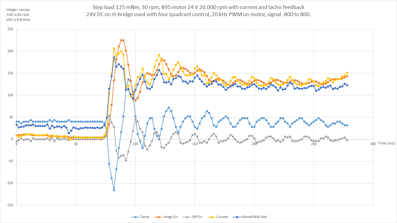
I think, that the oscillations you see in signals after the step is due to a mechanical resonance inside the spring pulling in the webbing. It is likely the center part of the spring moving up and down. It cannot be changed by altering the controllers amplifications. I think the controller response is quite fast, and the speed is restored within 25 ms.
I have been looking a couple of videos regarding the speed control involved with motors for drones. This is one of them:
https://youtu.be/RXy00orSpfU&t=411
There seems to be a problem related to how fast you can change the motor and propeller speed of a drone. It makes me ask:
-
Do the ESC perform active regeneration breaking of speed? Do it only got one quadrant (speed and torque) motor control or can it make two quadrants?
-
Is the ESC somewhat limited in how fast it can change speed of these motors? What is the bandwidth of the speed control loop used for drone motors?
Yes, most modern ESC can do active regeneration, but it’s rarely used in drones. Drones use active braking, though. The energy recovered is too low to be worth using full regen, active braking is all that’s needed.
Up to 32KHz, most drones are limited to that speed due to the IMU timing. Modern ESC use protocols like Dshot600 and Dshot1200 to speed things up
I guess this might be due to how the control algorithm typically is made. For brushed DC motors it is quite easy to make four quadrant control of the motor, and then the regenerative braking is much easier than to switch to some other special breaking condition. With FOC you should be able to control the current with right magnetic field angle to perform max torque in any direction.
But it might be so, that there is no speed loop, and the motor is controlled a bit like a stepper motor. Then performance needs to drop.
I do not mean PWM frequency.
Assume that you got a reference speed signal to the ESC, and you superimpose a sine wave signal with a frequency, f. Then you measure the actual speed of the motor, and you will find that the speed vary with the same frequency, f. At low frequencies, the speed will just follow the commanded reference signal. But when you increase the frequency, at some frequency the speed will not change that much anymore. The speed loop bandwidth frequency is when the speed change amplitude dropped 3 dB or to about 0.7 times the low frequency change value. I hope it makes sense.
No, That is made because the amount of regen is trivial, and not worth the complexity. I’m sure that full size flying machines use regen, but on a drone the amount of energy recovered given the trivial mass of the propeller is just not worth it. Active braking, yes. Regen, pointless.
Neither do I ![]() The flight controller sends commands to the ESC every 31.25 µs (most drones are happy with 8KHz, 125 µs, but the flight controller and ESC can go as high as 32KHz). When you look at some high performance FPV drones (like https://www.youtube.com/watch?v=9pEqyr_uT-k), every fraction of a msec matters, so those are the PID loop frequencies. Every loop, the flight controller sends an update to the ESC, which is turn runs at much higher PWM to make things work
The flight controller sends commands to the ESC every 31.25 µs (most drones are happy with 8KHz, 125 µs, but the flight controller and ESC can go as high as 32KHz). When you look at some high performance FPV drones (like https://www.youtube.com/watch?v=9pEqyr_uT-k), every fraction of a msec matters, so those are the PID loop frequencies. Every loop, the flight controller sends an update to the ESC, which is turn runs at much higher PWM to make things work
I have never opened the BLDC-8015A-5 and analyzed the electronics. But I also think that the control of the motor driver is not really sophisticated. But the control is definitely better than a universal motor.
The ST-Link on my F429ZI Nucleo board was temporarily broken. That’s why I had to switch to the G0 board. I will now continue with the F429ZI.
A sewing machine generates quite strong load peaks. My hope was that with current sensing the motor would run more smoothly.
Current sensing still doesn’t work really well. If I specify a target current in voltage mode, then my power supply shows exactly the target current.
In DC current mode or FOC current mode, the displayed current is significantly smaller than the target current.
Does anyone have any idea what is causing this behavior?
The motor test bench is pretty cool. Instead of a round disk you could also use a cam. This could be used to simulate the load peaks on the sewing machine.
What advantages do you see in using a simple brushed DC motor over a BLDC motor?
Thanks. I made a bit more detailed video about this test bench, if you like to see more. Its primary use have been to test universal motors for sewing machines:

I think the primary focus for a motor test bench is to be able to measure torque and speed and measure the input voltage, frequency, current and power to the motor at test in a steady state condition. Measurement of some dynamics have not been the primary focus. I think it will be difficult to create a specific defined measurable load change with a cam. The final use with a sewing machine will be the ultimate test to evaluate for load variations.
I have tested quite many universal motors for household sewing machines with this test set up, and variations are quite substantial and not that much related to marked values on motor. Universal motors are still quite cheep motors and the control electronics is cheep. They are still used in many applications. Used with proper gearing to a sewing machine and perhaps with a speed feed-back signal, these motor are still a decent and cheap alternative for a sewing machine. The test you see here is using an universal motor with altered gearing and tachometer feed-back:
https://youtu.be/uTB8DnyYAlA
I am not using drones, but I have seen several videos about the test set-up to test drone motors, and they rely on measuring the force that a propeller provide. I think they normally measure input voltage and current to the ESC (not to motor). It is an easy test set-up, but in my view, it is a far too simple approach to make proper evaluations of motors and propellers for that sake. You got so many other factors that can alter and influence test results like:
Variations in air density due to air temperature and air pressure.
Variations in actual propeller due to production variations of propellers.
The propellers got no specific data regarding torque, speed and thrust.
Variations in ESC performance.
No detailed measurement of AC current, voltage, power and frequency to the motor under test.
Motor condition like estimated temperature of the copper windings.
Too me it seems, that the drone users create a lot of problems for themselves by not separating performance of propellers to performance of motors. I know it is the combined effort that matters, but in design and evaluations I think that a separated approach would be beneficial.
Brushed DC motors are cheap, because they are produced in large numbers for battery driven tools. Furthermore, DC motors have been used a century for accurate servo control and they are very easy to control and their performance are very predictable. But they do have brushes, that may need to be replaced after some time of use. So I just like to keep things simple and cheep.
I have noticed the newer methods with FOC and BLDC motors with use of stronger magnets, and I have seen some videos of these drivers with remarkable low speed performance. I guess, that these motor drives will take over a larger part of applications, that use small motors. The older BLDC design with digital hall elements for commutations got in my view no significant difference to brushed DC motors, and they may actually be worse, because 6 commutations each electrical cycle is a not that much, and cause significant torque variations.
The FOC methods are still new to me, and I just like to study them a bit more, and perhaps make a drive for evaluation. That is why I started this thread here, and I am glad that others got a similar interest.
I am just lost here by the terms, so I like a bit of help to understand. Is G0 some versions of the STM32 processors? What is ADC in this context?
Don’t worry about the technical terms, that was more for the other SimpleFOC members who comtribute to the library.
Current sense is only compatible with the following architectures:

Different conversations are becoming interleaved here, but this thread is full of valuable insights and information, so I hope people are still able to follow ![]()
I think this is expected:
- in FOC current mode, the phase currents are not the same as the PSU (DC Link) current. This is normal, the voltage and current seen by the phases are different, the motor is an induction machine, has BEMF, and acts as a kind of buck or boost converter depending on what it is doing.
- what is expected is that the power level (Watts) input is the power level output, minus inefficiencies in the drive and friction.
- the DC current mode I would expect to work as you do, but it does not, due to a “bug” in the calculations. there is some discussion on it in the forum, GitHub and discord. The calculation has been changed for the next release version, but I am still not sure it will give you the same values as you see on the PSU.
- there is also the question of sampling and interpretation of the time-varying signals - the PSU may be displaying a RMS value, or doing some kind of filtering, while the values that come out of SimpleFOC are always point-in-time measurements, in some cases filtered by our low pass filter class.
Yes, STM32 MCUs come in a bewildering array of “Series” and “Lines” and a large number of package and memory configurations within each line ![]() you have more choices than you can make sense of.
you have more choices than you can make sense of.
The G0 Series includes the G0x0 (“Value line”) and the G0x1 line, which in turn include 310 different MCU models like the STM32G071KB etc… each one has a different chip package, ram memory, and/or flash memory configuration. ![]()
G0 Series MCUs are lower priced, lower powered generalist 32bit MCUs, and employ a ARM Cortex M0+ core, at up to 64MHz.
For motor control with FOC they are adequate, but not high performance MCUs.
ADC is the analog to digital converter of the chip - used in the current sensing, it converts analog voltages into digital values for use by the application code. It’s a complicated peripheral to use in the context of motor control.
For somebody who knows next to nothing about drones, you seem to be making quite a lot of (bad) assumptions ![]() . People who manage to fly at more than 240mph (360kmh), or lift insane weights, or fly for hours on small battery packs do understand and measure all those things (which, let’s be honest, are pretty easy to measure). But, no matter what, static tests are always limited: one thing is to measure how a propeller behaves in free air when static, another the dynamic performance of that same propeller when moving at 200+ mph in turbulent air
. People who manage to fly at more than 240mph (360kmh), or lift insane weights, or fly for hours on small battery packs do understand and measure all those things (which, let’s be honest, are pretty easy to measure). But, no matter what, static tests are always limited: one thing is to measure how a propeller behaves in free air when static, another the dynamic performance of that same propeller when moving at 200+ mph in turbulent air
Good quality motors (e.g. T-Motor) and good propeller makers publish specs. The majority of users are happy with measuring trust with a specific esc+motor+propeller to see if they have enough lift for their application, to check for efficiency per watt, or to do A-B comparison (e.g. how a different propeller works with the same esc+motor). Those are the ones using the simplified test harnesses using a kitchen scale. There’s not much else a hobby drone builder needs to care for 99% of the cases. Efficiency (i.e. how long you can fly on a battery) tends to be the main parameter. When flying, adding weight is bad, not just for endurance, but also for dynamic performance. So they want to measure how much lift a specific esc+motor+propeller can generate for a specific current. And swap components as needed, especially propellers (the number of blades can have significant impact, beyond the other measurements of pitch, diameter and shape)
The people designing motors, esc and propellers use much more sophisticated test harnesses, but you are unlikely to see much about those due to IP concerns. High performance manufacturers sell optimized combinations of esc+motors+propellers designed for specific usages (heavy lift, speed, etc). like DJI’s tuned propulsion systems (example E1200 Pro - DJI)
Drone motors and ESC have completely different designs, goals and optimization parameters compared to industrial motors and there’s no point comparing them
Thanks for your comments robca. I will reply to things about dynamics in another post, so this will only be about more general issues.
It was fun to watch your linked video about this amazing high speed small drone. I am also stunned by the huge number of views (13 mill.).
Perhaps I should have kept by big mouth shut, when I know almost nothing about drones. But as an outsider studying the technical information easy available on internet, it was what came to my mind. I am not that far away either, because In my youth i have been flying RC aero planes and later got pilot certificate for gliders and aero planes. Furthermore, I have been in electronics development and testing for many years.
I guess I have mostly seen the hobby segment of information, and you are right, that of cause the more professional people in this business must be using better methods. I have just seen lots of the cheaper motors sold only by stating their specifications based on the thrust by a few propellers, and it just seems too simple to me even for a hobby drone designer.
I noticed this test stand sold, that also measure motor torque and speed, and to me it is a step in the right direction, but I guess this test bench will be to expensive for the hobby designer or technical drone YouTuber:
Drone motor test bench with torque and speed measurement
I can understand that drone motors are different, but why should the ESC for drones be that much different to an ESC for industrial applications?
Super-low weight, extra small size, lack of regen, high RPM, no hall sensors, no encoders, specialized bidirectional communication with the flight controller (Dshot600, etc some industrial drones use CAN). Each esc is optimized for a specific use (e.g. racing, video, heavy lift, etc) in order to minimize size and weight (some weigh 1g). Position control or torque control are not needed (torque might for some industrial, heavy weight drones, but very uncommon in hobby drones). Like the motors, most of the drone esc won’t work in a static application: they all rely on the propeller wind as part of their heat sink design
They have nothing in common with a generic industrial motor controller, where size and weight almost don’t matter. And most industrial controllers have some sort of UI, which is non-existent for drones where the flight controller is in charge
Just about the only thing in common is that they have 3 phases to control a BLDC motor
I’d add to this list that many drone ESCs are also unidirectional in the sense that their input can control the speed of the motor in only one direction…
And that they lack management of over voltage conditions because the drone batteries just suck it up…
To me, the data protocol for sending reference speed information do not matter much. It just needs to be able to send the date sufficiently fast, and I think 8 kHz will be sufficiently fast by far. I do not think, that it should limit the real dynamics of a drone motor drive response.
When you evaluate and study the dynamics of systems, there is two methods commonly used. One is the step response and the other is the frequency response. When I was talking about bandwidth of the control loop, it is about the frequency response. But now I shall try to focus on speed step response:
I think I have watched about 20 videos about test of drone motors, and none of them go into measuring the dynamics. They only measure the static responses. I also see a lot of concern regarding the dynamics, and therefore I’am surprised to see, that none of the more hobby minded people do measure the dynamics.
I found this video in which, you are able to hear steps in speed, and when you carefully listen to it, I can hear that the change in speed is not instand, and the changes most likely lasts about 50 ms, which in my view is rather slow:

This is a 40 second video from my test set up, with a similar test with speed test response:

And here is the actual plotted data for such a step response from my test:
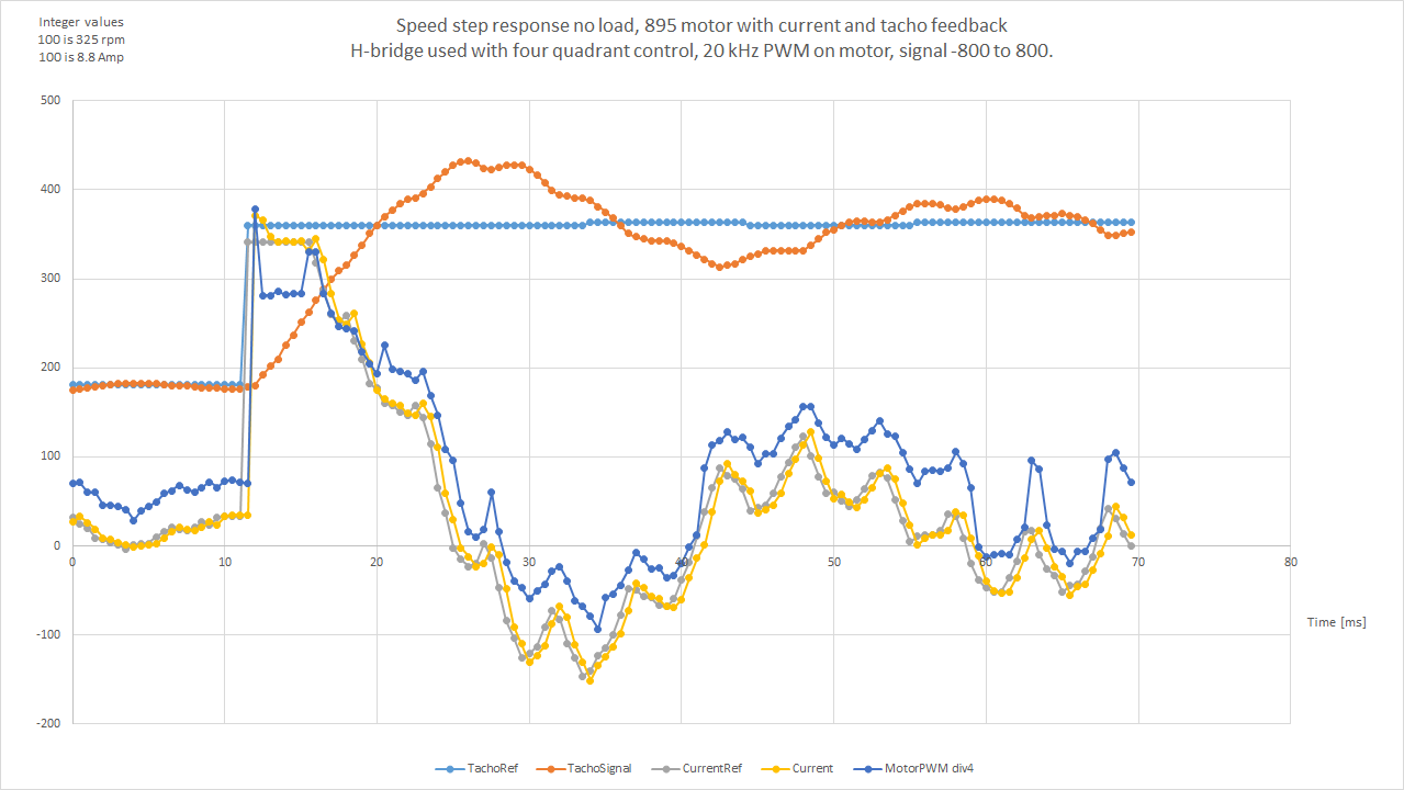
The light blue line shows the reference speed or ordered speed to the controller for speed. The orange line show the actual measured speed of the motor. The change is from about 600 rpm to 1200 rpm. You see, that it takes about 8 ms for the motor to reach the new speed, but it takes some more time for the speed to stabilize on the new speed.
To measure speed of a motor is simple, and I think most technical hobby designers of drones should be able to do that. When the dynamics is important, then I just recommend to make this simple kind of test. I guess, that the ESCs used for drones could very well have different performance on this issue.
This is just a time zoomed plot from the same test I did:
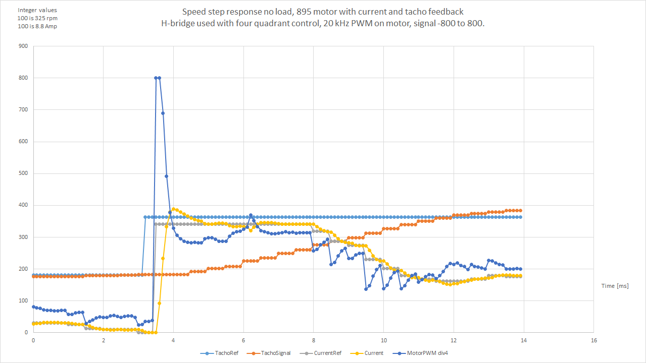
Perhaps you need a bit more information regarding the other curves in the plots. The controller got two closed loop controllers. One inner loop that controls the motor current, and the motor current and correction is done each 100 us. The speed is measured every 500 us and is used for an outer control loop providing a refence current signal to the current controller.
First you see, that the reference is changed (light blue value). Within 500 us the speed controller sees that and change the current reference (gray curve) to a max value of 341. It is a max current value of 30 amps to the motor I have put in software in order to not make cause too big currents. 100 us later the current controller sees the new wanted current, and it changes the PWM signal to max (it is 800). That means that the motor will be given a max voltage of 24 VDC constantly to increase current as fast as possible. The yellow curve shows the actual motor current, that start to rise. The current rise time is limited by the self inductance of the DC motor. The actual current overshoots about 10 % and stabilize to the refence current of 30 Amps. When the current is reached, the PWM voltage to the motor is reduced in order to keep the motor current at the required value. In the next about 8 ms you see that the speed of the motor increase, and the limiting factor here is the current provided and the moment of inertia of the motor and wooden wheel. Later on the motor current also becomes negative providing negative torque in order to correct the speed, that got too high.
I really don’t understand why we are talking about drone motors and esc given how irrelevant they are here. But, just in case, that test is using an esc driven by an old-style PWM control signal, which is a signal with a 20ms period (which is also very likely a slow esc). So, yes, with a 20ms-cycle control signal, a motor speed change is slow. Also, a relatively small motor driving a big propeller with enough mass to slow things down. And that video only focuses on trust, which doesn’t need a faster loop cycle or anything else. As I mentioned before, for certain applications trust and efficiency is all that matters, and everything else is a waste of engineering time. You can’t take a random YouTube video and assume it’s relevant.
I’m talking about modern controllers using Dshot600 or Multishot, with ~25us control loop and optimized motor/propeller for high speeds. Thousands of engineers in the FPV community incuding well funded companies (DJI, Red Bull, etc) have spent significant time and engineering talent to ensure that a modern FPV drone can work with 32kHz control loops, and they optimized every single element: from radio protocols with negligible latency, to flight controllers, to ESCs and motor/propeller combinations. I posit that they understand the problem better than you do and they spent their resources wisely, considering the progress in the last 10 years.
This is my last answer here, because it’s completely OT and irrelevant to the main topic. Apologies for being OT
Fast speed control is important for the control of sewing machine motors. It seems also to be important for drones as well. Therefore a discussion of this is in my view not off topic.
Up to now, I have not seen any test data, that actually shows how fast the speed is changed on modern FPV drone motors. Can anyone show me how to find such data? A fast data transmission protocol and a fast update frequency of the control loop do not make fast speed changes on the propeller by themselves. It require intelligent software as well. Of cause you do not have a 10 % speed change of a drone motor within 1 ms.
I have seen many technical videos about drones, that focus on the size (stator volume) of the motor in relation to propeller size to provide guidance for drone builders, and they talk about responsiveness and the dynamics to be important. But they actually provide no data on how fast the motor speed change actually is.
It might be, that all ESCs for the FPV drones already are fully optimized the past 10 years, and there is no need to look into that for the sake of drones. But for reference I am very interested in seeing real measurement data on how fast the speed changes are, because it is relevant for what might be possible for an ESC for a motor to a sewing machine.
There can be other reasons, that the dynamics of the speed control for a drone motor do not apply to sewing machines, and it relates to the fact, that drone motors generally operate at high speeds, and typically from half too full rpm speed of motor. For a motor for a sewing machines, you like to see the fast speed response at low speeds.
Yes I agree with you. If you want to compare motors and controllers with each other, then a static load or a single load step is much more suitable.
The speed control of the universal motor looks really good. What maximum speed does the sewing machine reach?
Personally, I think that drone motors and their controls are not a good reference for sewing machine motors. Drone technology is far too focused on a specific use case.
Brushed DC motors can also be controlled completely analog using operational amplifiers. In my opinion, this is the coolest thing about brushed DC motors.
I don’t think it’s that important whether the motor is brushed or brushless. A motor for a sewing machine does not have extreme requirements.
Ah, that makes sense. Do the two PID controllers always have the same parameter set in FOC Current Mode? And what is the best way to retune these two PID controllers?
In my opinion the speed overshoot of the controller is a bit too strong. Otherwise the controller looks really great.
What about the motor temperature? The motor certainly generates 100 watts of waste heat. Does the motor manage to permanently keep the temperature below 100 degrees Celsius?
I don’t know if this helps you, but there are tuning guides for the PID controllers of FPV drones. You can often see data about the response time of drones: