Mosquito Board / New design

I’ve done that successfully quite a few times. You just put some foil down (or have a dedicated pot), and put it on high for 2-3 minutes, watching very carefully. I give it a 5 count once everything appears to have reflowed, then take it off heat.

I’m using a small aluminum 260C hotplate made for reflowing though, and a 14x14" ceramic floor tile that’s my go-to $2 heat resistant tabletop :slight_smile:

Honestly, I think hot-air rework is maybe a little more dangerous for hobbyists since there’s always the temptation to wave your hand in front of it to check if it’s on (the answer sometimes will be “YES! OWW!”). I might just be bad at hot air reflow though. My LEDs tend to get a little crispy, and components like to slide around if I’m not careful in the airflow.

2 Likes

Please share some pics of your robots when they’re ready… I’m sure I’m not the only one who would love to see, if you feel like sharing :slight_smile:

@Magneon

Interesting. Combat robot, that board maxes out at 2A, and the robots I’ve seen throw some really high power out. Is it going to be sufficient? May be the micro-bots, but those are like 150g, so which category you play?

The ones I’m doing are 1lb and 3lb weight class (ant and beetle). For those, I tend to run higher voltage (4S+) which is a bit unusual, and I’ve previously been using (mis-using) 12V/1k RPM N20 motors (2-4 for 1lb, and 4-6 for a 3lb robot). They draw about 1A each short circuit.

Lately I’ve been playing with moving to brushless hub motors, but unfortunately that’s not really a well serviced area in the hobby BLDC market. Ideally I’d want 4-8 ohm resistance motors that are most of the way towards a typical 12ohm small 3-4S gimbal motor, but with slightly beefier windings and slightly higher kV rating.

Unfortunately those don’t exist :confused:

The problem I’ve got is that cheap sensorless hobby ESCs tend to have startup/cogging issues around their bottom 10-20% of the throttle. For a differential drive robot trying to steer precisely (for example rotate on the spot to face the opponent), that’s really annoying. A human operator can overcome it (expand the deadband on their stucks, and close the loop by eye), but one of my bots has a PID auto-aim system that tries to face the opponent. This is already needlessly complex, but since I’m having a lot of fun I’m doubling down and trying to fix the control problem (or at least improve it).

The other options are to have a nearby PC run SLAM to close the loop (which is fine by the rules, but IMO kind of against the spirit since the PC’s safety isn’t “in the ring” like the other bot), or to use something like mouse optical flow sensors (a pair of them by the sides) to track actual motion, but those both have the drawback of not being part of the motor control loop.

There’s a VESC project by a UK team that’s close to what I want, but it’s $80/unit (which is being sold nearly at cost), and I’m typically looking to spend $80-200 on 1lb, and maybe twice that on 3lb bots.

So here I am :slight_smile:

The motor I’m using on my latest ant weight is a $5 265kV 4S rated 12.5 ohm 19g 1807 can gimbal motor that’s a little heavy but otherwise pretty much perfect for a direct drive, or single stage reduction 2-4WD ant or beetleweight. I’m probably not going to use this board for my next competition, but I’m gearing up to have it in the wings for the following one (maybe this coming winter).

One of the “neat” things about combat robots is that a lot of the voltage ratings, MTBF numbers, etc. become a lot more flexible. It’s got to last 1 or more 3 minute bouts, and after a few of those if it still works, that’s a huge plus. I’m a lot less worried about overheating, and as a result can get away with running motors 10-50% over their rated voltage, trace width heat dissipation can be +80C, and all sorts of silly things that are typically bad ideas :slight_smile:

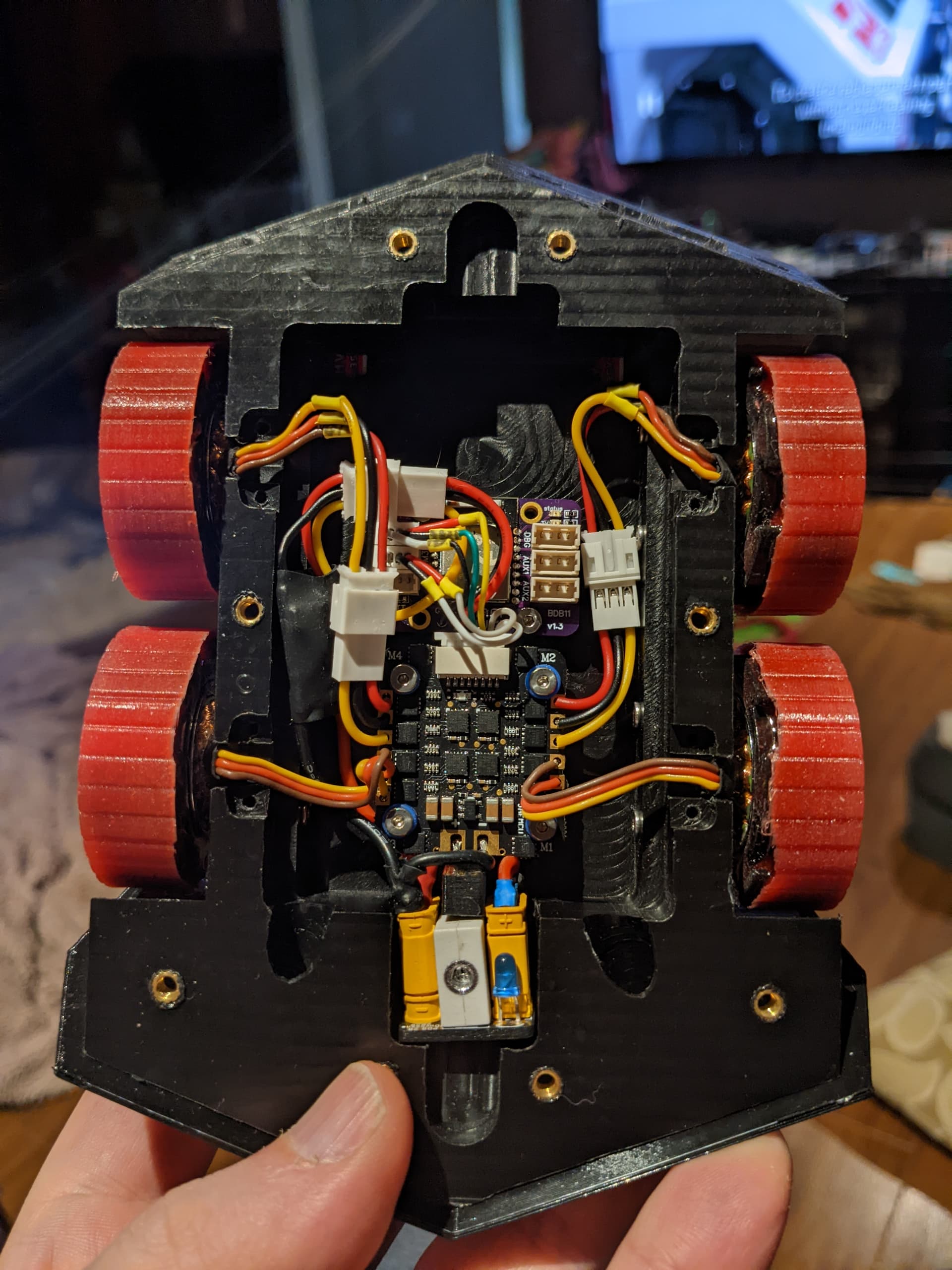
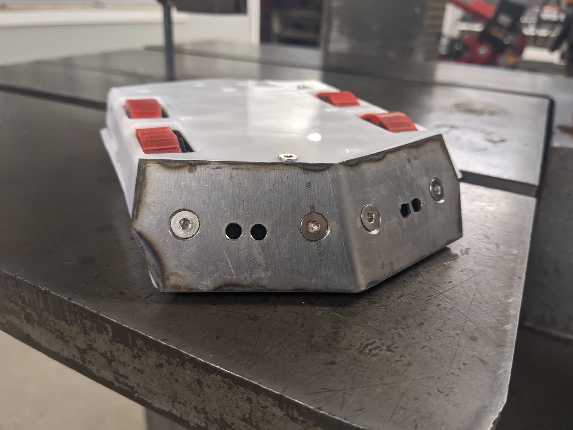
Also, for photos, here’s the 1lb X+Y radially symmetrical, semi-autonomous wedge bot I’m working on:

The current version uses:

  • 4x D1807 unbranded hub motors
  • Custom polyurethane wheels (Shore A 35)
  • 1" HDPE billet frame (black)
  • 3mm HDPE top/bottom armor (white)
  • 1.2mm hardened 4130 front/back wedges
  • 4S 350mAh LiPoHV batteries (in a tray on the bottom opposite the electronics)
  • Custom NRF52832 based control board
  • Custom SAMD21 based sensor processing board
  • 4in1 BLHeliS drone ESC
  • 4x VL53L5 3d ToF lidars (2 front, 2 back)
6 Likes

Right. I also need something like that. The closest I found was hoverboard motors. Obviously not the right choice for you for a small robot.

May be there is a market opportunity to create/design some?

That’s cheating. Also the delay to transmit real-time telemetry may be a deal breaker.

Seeing some bouts, those robots are disposable anyway. At the end there are smoking bits and pieces all over. Interesting use cases. You just want it to survive 10 minutes action run time.

In this picture, would the Mosquito board be sufficient for the wheels? You will need 4 boards then.

Cheers,
Valentine

The design I had in mind would only be 2WD, with belts driving the second set from the first. I’d throw in a 2:1 or 3:1 reduction and not run them as hub motors most likely though since that would give me more torque and probably less weight. It would require a complete redesign of the middle of the bot unfortunately but I’m considering it.

I was considering re-winding some off the shelf motors if I really want to get exactly what I’m after. It’s tedious but I don’t really see another way. Nobody sells laminated stators and matched magnets+cans below 40-50mm diameter (small robotics actuators). Most of the community that’s moved to brushless is using 2208 or 2212 900-1000kV for 3lb bots, with either a single stage reduction or a 22mm 2 stage planetary set.

For now I’m interested to see if better low end control is enough to keep doing direct drive.

Also, I completely agree that running software on nearby a laptop is against the spirit (at least the spirit I enjoy) in combat robotics, but it’s absolutely allowed by the rules everywhere I’ve competed. Nobody’s done it, so it’s never come up. There are rules about safeties and radio technologies, but no definition restricting how powerful the processor on the other end of the radio can be. There’s already quite a spread between a 1999 $50 3 channel rc controller, and a $799 openTX monster.

The funny thing is that the best bots are typically just well put together and expertly driven. All the fancy stuff I do just adds more points of failure and distracts me from practicing driving.

1 Like

Gimbal motors are often terminated wye for lowest kv, so converting to delta will likely get into the resistance range you’re looking for.

1 Like

Love your robot, this sounds like such a fun project!

However, I disagree that there’s no 5Ω motors… 4-7Ω isn’t even so uncommon for gimbal motors I would have said:
https://store.cubemars.com/goods.php?id=1133

That’s one I found quickly now, but I’m sure if I dig in my box at home I’ll find several more…

Is it 5Ω phase-to-phase you’re looking for, or 5Ω actual phase resistance, which as dekutree has pointed out is dependent on the winding type…

Let me turn the problem around. Instead adapting your design for existing boards, let’s flip the use case.

If you are hypothetically provided with the perfect driver board that would ideally suit your best design, what would that be? Imagine you are Aladdin rubbing the proverbial lamp and the genie grants one wish.

Describe the driver board that would match your best design. Don’t think “this could not be done so I won’t need it”. Think “I want this regardless of if it’s possible or not. I want the board to read my brainwaves. I want the board to predict the future. Etc…”

Cheers,
Valentine

1 Like

The main constraints in small combat bots are weight > space > price (within reason).

Ideally I’d want enough torque for 2-4 wheels to drive a 1lb or 3lb bot with enough overhead to push around the other bot (same weight). This requires winning the traction game (polypropylene on plywood or steel). Easy if the opponent uses foam wheels, or is 2WD vrs my 4WD (since they’re giving up part of their traction to their bot dragging). Complicated by uneven damaged floors, and dust reducing friction.

4mm-5mm shaft for durability (3 is acceptable but a little risky).

Direct drive is ideal, since it reduces space, and allows for a hub motor (even more space savings).

Direct drive RPM topping out around 3-4k (for a 1.5" wheel) at 4S (200-300kV?).

Motor driver that can ramp up and down to full speed reliably regardless of how aggressively the throttle is used (this is my hope for FoC+sensor handling the low end of the throttle). Currently I manually insert some dead time on throttle reverse, to prevent the blheli_s from freaking out, since going from 20% throttle, to -20% doesn’t make its sensorless configuration happy.

I really like the idea of all-in-one motor drivers in the motor mount, especially if there’s an integrated sensor configuration. I’m keeping an eye on this dual hall sensor thread: https://community.simplefoc.com/t/40-cent-magnetic-angle-sensing-technique/1959 since it seems like it might be a good fit.

I think it’s all doable, however it seems likely that the result will be $150 custom machined, hand wound and hand made per motor :wink:

The other thing I’m interested in is the possibility of doing a 1lb walker bot. This is very impractical because currently it would have to use servos, which are too fragile and can’t survive a limb being backdriven by a weapon impact. If there was a small and cheap enough 4-6 gimbal motor configuration that could move a biped, or 6-9 for a tripedal bot it would be really neat. A “true” walker gets a weight bonus of 200% (allowing a 2lb walker in a 1lb match). True being typically defined as “not involving continuous rotation in a walking pattern”, so excluding cam based mechanisms that simply convert continuous rotation into linear motion. Those typically get half the bonus (“shufflers”), similar to vibration bots and most gyro-walkers. The limitation seems to be that any mechanism must involve motors reversing direction as part of the walking motion.

As a third topic, my boards arrived! I

I may attempt soldering the first one today.

3 Likes

Great! Please be careful. :crossed_fingers: :crossed_fingers: :crossed_fingers:

I’d be interested in a version that provided the connector for https://www.tindie.com/products/smallrobots/as5048a-encoder-board-for-robots-motor-control/ I believe there will be various ‘flavours’ of these encoders all using the same connector

You can DIY a connecting cable with 1.25mm or 1.27mm pitch on one side and 1mm pitch on the other. There is no good way of selecting a standard connector. The JST-SH is 1mm. However the 1.27/1.25 pitch (1/20th of an inch) is more widely used and easier to find and solder. Also, the Mosquito project is shared, and swapping and re-routing a connector is relatively easy.

Cheers,
Valentine

1 Like

@Valentine what’s it like driving those little micro outrunners? I’ve always used the higher resistance gimbal motors but it would be interesting to use the outrunners if they will indeed run a bit faster?

High current and little output. It’s more of a curiosity and a toy rather than anything serious. I had to lower the current limit to make it work with the DRV8313.

Cheers,
Valentine

1 Like

I received my boards and tested it with the program from the Mosquito BLDC UserGuide. All working very well.
I soldered the SC60228DC chip to it and I wanted to test it with the program from the example menu of simpleFoc (esp_posistion_control). I modified the sketch with the pin definition from the UserGuide with the SimpleFOCDriver for the SC60228.

#include <SimpleFOCDrivers.h>
#include <encoders/sc60228/MagneticSensorSC60228.h>
#define SENSOR1_CS PA4  // some digital pin that you're using as the nCS pin
MagneticSensorSC60228 sensor(SENSOR1_CS);

When I compile the sketch I get an error message stating that the program does not fit into the FLASH:

/Users/xxxx/Library/Arduino15/packages/STMicroelectronics/tools/xpack-arm-none-eabi-gcc/10.3.1-2.3/bin/../lib/gcc/arm-none-eabi/10.3.1/../../../../arm-none-eabi/bin/ld: esp32_position_control.ino.elf section `.rodata' will not fit in region `FLASH' /Users/xxxx/Library/Arduino15/packages/STMicroelectronics/tools/xpack-arm-none-eabi-gcc/10.3.1-2.3/bin/../lib/gcc/arm-none-eabi/10.3.1/../../../../arm-none-eabi/bin/ld: region `FLASH' overflowed by 5988 bytes collect2: error: ld returned 1 exit status exit status 1 Fout bij het compileren voor board Generic STM32G0 series

Any idea what I can do to eliminate this error? Is the flash memory to small for this sketch?

Thanks for the help

/**
 * ESP32 position motion control example with magnetic sensor
 */

 // MOSQUITO BOARD
// SELECT STM32G031K8Ux

#include <SimpleFOC.h>
#include <SimpleFOCDrivers.h>
#include <encoders/sc60228/MagneticSensorSC60228.h>

#define SENSOR1_CS PA4  // some digital pin that you're using as the nCS pin
MagneticSensorSC60228 sensor(SENSOR1_CS);

#define serial1_tx_pin PA2
#define serial1_rx_pin PA3
// DRIVER PINS
#define PWM1 PA8
#define PWM2 PA11
#define PWM3 PB3
#define DRVENABLE PA15
#define DRVFAULT PB4
#define DRVRESET PB5

BLDCMotor motor = BLDCMotor(6);
BLDCDriver3PWM driver = BLDCDriver3PWM(PWM1, PWM2, PWM3, DRVENABLE);  // STM32G031K8Ux + MOSQUITO

HardwareSerial Serial1(serial1_rx_pin, serial1_tx_pin);

// angle set point variable
float target_angle = 0;
// instantiate the commander
Commander command = Commander(Serial1);
void doTarget(char* cmd) { command.scalar(&target_angle, cmd); }

void setup() {

  // initialise magnetic sensor hardware
  sensor.init();
  // link the motor to the sensor
  motor.linkSensor(&sensor);

  // driver config
  // power supply voltage [V]
  driver.voltage_power_supply = 12;
  driver.init();
  // link the motor and the driver
  motor.linkDriver(&driver);

  // choose FOC modulation (optional)
  motor.foc_modulation = FOCModulationType::SpaceVectorPWM;

  // set motion control loop to be used
  motor.controller = MotionControlType::angle;

  // contoller configuration
  // default parameters in defaults.h

  // velocity PI controller parameters
  motor.PID_velocity.P = 0.2f;
  motor.PID_velocity.I = 20;
  // maximal voltage to be set to the motor
  motor.voltage_limit = 6;

  // velocity low pass filtering time constant
  // the lower the less filtered
  motor.LPF_velocity.Tf = 0.01f;

  // angle P controller
  motor.P_angle.P = 20;
  // maximal velocity of the position control
  motor.velocity_limit = 40;
  // use monitoring with serial
  Serial1.begin(115200);
  // comment out if not needed
  motor.useMonitoring(Serial1);


  // initialize motor
  motor.init();
  // align sensor and start FOC
  motor.initFOC();

  // add target command T
  command.add('T', doTarget, "target angle");

  Serial.println(F("Motor ready."));
  Serial.println(F("Set the target angle using serial terminal:"));
  _delay(1000);
}

void loop() {

  // main FOC algorithm function
  // the faster you run this function the better
  // Arduino UNO loop  ~1kHz
  // Bluepill loop ~10kHz
  motor.loopFOC();

  // Motion control function
  // velocity, position or voltage (defined in motor.controller)
  // this function can be run at much lower frequency than loopFOC() function
  // You can also use motor.move() and set the motor.target in the code
  motor.move(target_angle);


  // function intended to be used with serial plotter to monitor motor variables
  // significantly slowing the execution down!!!!
  // motor.monitor();

  // user communication
  command.run();
}

Yes, you need to try reducing the size somehow. Writing small code is a challenge. This is a problem not only with the Mosquito board but other boards, too.

Try removing the hardware serial portion of the code, the serial eats up a lot of memory, and control the motor with other means.

I’ve seen other people using an analog pin to control the motor instead of serial, or i2c perhaps?

I remember @runger had some other suggestions about reducing the code size, you may want to ask him.

Cheers,
Valentine

PS Also I’ve seen others use a digital pin to control the direction and PWM analog to control the speed. When I get back from vacation I may try to write a tutorial with sample code, to avoid the serial control.

Thank you for using the Mosquito board.

Hey, how much RAM does the MCU have? Fitting SimpleFOC into 64kB on STM32 is a challenge, but it should be possible.
You can try disabling debug with the flag:
-D SIMPLEFOC_DISABLE_DEBUG
That should compile away all the debug output, saving a few bytes.

You can check your own program code in main() and setup() and remove anything using much space, if you have anything like that.

There is also a SimpleFOC minimal version, but it might be a bit of work to get running.
Other ideas include setting compiler options to -Os (optimize for size) and disabling USB, if enabled.

When using SimpleFOC on STM32 MCUs having a chip with 128kB (or more) flash will spare you a lot of headache and give you more room for your own program code…

The G8 has 64k flash.

I never had good experience with the option flags, but disabling the USB certainly may help.

Unfortunately the small 4x4mm G031 chips do not have that much flash, 64k is the max, it’s a trade-off.

Cheers,
Valentine

Thanks @runger and @Valentine for your suggestions and help.

Adding #define SIMPLEFOC_DISABLE_DEBUG had no effect on the code size.

I took the road to use the SimpleFOC minimal version concept. I gathered all needed libraries from the main branch of the Arduino-FOC Repository and put them in the Arduino program folders. I had to add the communication folder to avoid SimpleFOCDebug errors. So, this is the file structure.

├── src
│   ├── BLDCMotor.cpp
│   ├── BLDCMotor.h
│   ├── common
│   │   ├── base_classes
│   │   │   ├── BLDCDriver.h
│   │   │   ├── CurrentSense.cpp
│   │   │   ├── CurrentSense.h
│   │   │   ├── FOCMotor.cpp
│   │   │   ├── FOCMotor.h
│   │   │   ├── Sensor.cpp
│   │   │   ├── Sensor.h
│   │   │   └── StepperDriver.h
│   │   ├── defaults.h
│   │   ├── foc_utils.cpp
│   │   ├── foc_utils.h
│   │   ├── lowpass_filter.cpp
│   │   ├── lowpass_filter.h
│   │   ├── pid.cpp
│   │   ├── pid.h
│   │   ├── time_utils.cpp
│   │   └── time_utils.h
│   ├── communication <— added
│   │   ├── SimpleFOCDebug.cpp
│   │   └── SimpleFOCDebug.h
│   ├── drivers
│   │   ├── BLDCDriver3PWM.cpp
│   │   ├── BLDCDriver3PWM.h
│   │   ├── hardware_api.h
│   │   └── hardware_specific
│   │       ├── stm32_mcu.cpp
│   │       └── stm32_mcu.h
│   └── sensors
│       ├── MagneticSensorSC60228.cpp
│       ├── MagneticSensorSC60228.h
│       ├── SC60228.cpp
│       └── SC60228.h
└── stm32_bldc_magnetic_spi.ino

The Arduino code as it is now:

/**
 * Comprehensive BLDC motor control example using magnetic sensor
 * 
 * Using serial terminal user can send motor commands and configure the motor and FOC in real-time:
 * - configure PID controller constants
 * - change motion control loops
 * - monitor motor variabels
 * - set target values
 * - check all the configuration values 
 * 
 * To check the config value just enter the command letter.
 * For example: - to read velocity PI controller P gain run: P
 *              - to set velocity PI controller P gain  to 1.2 run: P1.2
 * 
 * To change the target value just enter a number in the terminal:
 * For example: - to change the target value to -0.1453 enter: -0.1453
 *              - to get the current target value enter: V3 
 * 
 * List of commands:
 *  - P: velocity PID controller P gain
 *  - I: velocity PID controller I gain
 *  - D: velocity PID controller D gain
 *  - R: velocity PID controller voltage ramp
 *  - F: velocity Low pass filter time constant
 *  - K: angle P controller P gain
 *  - N: angle P controller velocity limit
 *  - L: system voltage limit
 *  - C: control loop 
 *    - 0: voltage 
 *    - 1: velocity 
 *    - 2: angle
 *  - V: get motor variables
 *    - 0: currently set voltage
 *    - 1: current velocity
 *    - 2: current angle
 *    - 3: current target value
 * 
 */
#include "src/BLDCMotor.h"
#include "src/drivers/BLDCDriver3PWM.h"
#include "src/sensors/MagneticSensorSC60228.h"

#define SIMPLEFOC_DISABLE_DEBUG

// SPI magnetic sensor instance
#define SENSOR1_CS PA4  // some digital pin that you're using as the nCS pin
MagneticSensorSC60228 sensor(SENSOR1_CS);

#define serial1_tx_pin PA2
#define serial1_rx_pin PA3
// DRIVER PINS
#define PWM1 PA8
#define PWM2 PA11
#define PWM3 PB3
#define DRVENABLE PA15
#define DRVFAULT PB4
#define DRVRESET PB5

// BLDC motor & driver instance
BLDCMotor motor = BLDCMotor(6);
BLDCDriver3PWM driver = BLDCDriver3PWM(PWM1, PWM2, PWM3, DRVENABLE);  // STM32G031K8Ux + MOSQUITO

HardwareSerial Serial1(serial1_rx_pin, serial1_tx_pin);


void setup() {

  // initialise magnetic sensor hardware
  sensor.init();
  // link the motor to the sensor
  motor.linkSensor(&sensor);

  // driver config
  // power supply voltage [V]
  driver.voltage_power_supply = 12;
  driver.init();
  // link driver
  motor.linkDriver(&driver);

  // choose FOC modulation
  motor.foc_modulation = FOCModulationType::SpaceVectorPWM;

  // set control loop type to be used
 // set control loop type to be used
  motor.controller = MotionControlType::torque;


  // contoller configuration based on the control type 
  motor.PID_velocity.P = 0.2;
  motor.PID_velocity.I = 20;
  motor.PID_velocity.D = 0;
  // default voltage_power_supply
  motor.voltage_limit = 12;

  // velocity low pass filtering time constant
  motor.LPF_velocity.Tf = 0.01;

  // angle loop controller
  motor.P_angle.P = 20;
  // angle loop velocity limit
  motor.velocity_limit = 50;

  // use monitoring with serial for motor init
  // monitoring port
  Serial1.begin(115200);
  // comment out if not needed
  motor.useMonitoring(Serial1);

  // initialise motor
  motor.init();
  // align encoder and start FOC
  motor.initFOC();

  // set the inital target value
  motor.target = 2;


  // Run user commands to configure and the motor (find the full command list in docs.simplefoc.com)
  Serial1.println("Motor commands sketch | Initial motion control > torque/voltage : target 2V.");
  
  _delay(1000);
}


void loop() {
  // iterative setting FOC phase voltage
  motor.loopFOC();

  // iterative function setting the outter loop target
  // velocity, position or voltage
  // if tatget not set in parameter uses motor.target variable
  motor.move();
  
  // user communication
//  motor.command(serialReceiveUserCommand());
}

// utility function enabling serial communication the user
String serialReceiveUserCommand() {
  
  // a string to hold incoming data
  static String received_chars;
  
  String command = "";

  while (Serial1.available()) {
    // get the new byte:
    char inChar = (char)Serial1.read();
    // add it to the string buffer:
    received_chars += inChar;

    // end of user input
    if (inChar == '\n') {
      
      // execute the user command
      command = received_chars;

      // reset the command buffer 
      received_chars = "";
    }
  }
  return command;
}

It compiles and the sketch uses 51432 bytes (78%). I had to comment out the row: motor.command(serialReceiveUserCommand()); because this causes a compilation error:

/Users/xxxx/Documents/Arduino/stm32_bldc_magnetic_spi/stm32_bldc_magnetic_spi.ino: In function 'void loop()':
stm32_bldc_magnetic_spi:138:9: error: 'class BLDCMotor' has no member named 'command'
  138 |   motor.command(serialReceiveUserCommand());
      |         ^~~~~~~
exit status 1
'class BLDCMotor' has no member named 'command'

I can’t find the cause of this error. Any clue? Thanks for the help

1 Like