MosquiNo - Yukon concept

I spotted the Yukon system from Pimoroni

I wondered about hacking the Mosquito board around to fit that footprint and started having a go here

The encoder header would be pin compatible with the @runger AS5048A

The target motor would be the Tmotor 2208 as I have a 3d print bracket stl, FCStd for that

I’ll continue playing around with it, but if anyone who knew what they were doing fancied it as a side project then that would be cool too.

Named MosquiNO in anticipation of Valentines exclamation when he sees what I’ve done to his board.

4 Likes

LOL you can do whatever fancy you fit, I’m here for the show.

Why do you need 6 of those? Sextopod? :rofl: :rofl: :rofl:

Cheers,
Valentine

1 Like

You might want to do a Sawppy for example, four would be a more common in a Mecanum bot

I see, more like a micro-rover type type of a thing? Cool. I’m looking forward to seeing progress.

Please come back and report.

Cheers,
Valentine

2 Likes

gnd

Did a bit more playing around. Can’t figure out why the whole right hand section won’t fill with a GND copper currently

1 Like

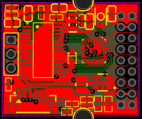
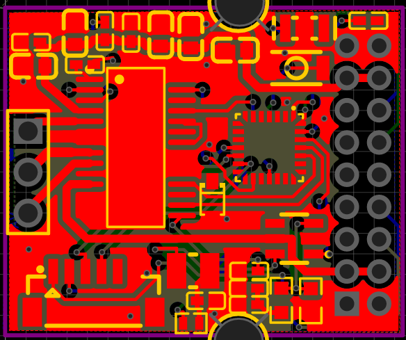
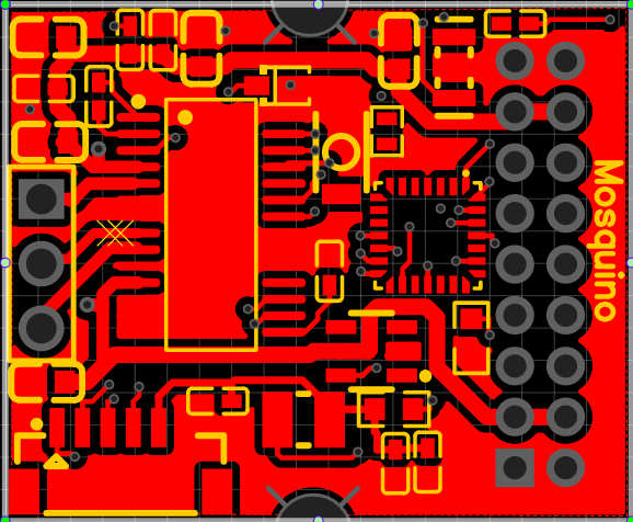
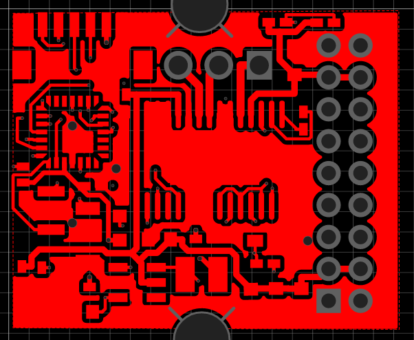
Your copper tolerance gap is too high. Set it to solid 150 microns. Also strategically place ground vias to connect to the bottom and form a single ground path. Let me know if you need step by step guidance. Also your traces are way too thin, etc, you definitely need work but one at a time. Also you are routing a power trace under the power inductor that’s a big no no, etc. etc.

Cheers,
Valentine

1 Like


improved?

This may have improved it slightly?

It’s better. Remove any traces under the inductor. Also one of the traces of the driver is kinda touching the other next lead, 4-th right from the top. Make sure you run DRC checks all the time.

Cheers,
Valentine

1 Like

Think the layout is starting to look a little saner

saner

No traces under the inductor

Better but I see some DRC failures.

Cheers,
Valentine

1 Like

Yeah it’s quite hard this!

I think part of my problem is poor component placement?

I tried this alternative without much success. Have you got suggestions for placement improvements?

If you have the inclination and it’s easier to drag stuff around to demonstrate, then please feel free, no expectation obviously.

Can you make your project shareable? I’m super busy but may have 10 to 15 min to spare.

Cheers,
Valentine

1 Like

I think it is already? I was able to file> save as from a separate account.

I’m still getting 73 DRC violations. Please clear those, clearances and incomplete connections. That’s way to many for me to resolve, I need to rework the entire board from scratch.

If you are unsure, there are educational videos you could watch on EasyEDA.

You need to get some hands-on self-training before you spend any money on manufacturing a board.

I can help, but cannot provide you with basic CAD/EDA training, not with this type of problems.

Cheers,
Valentine

1 Like

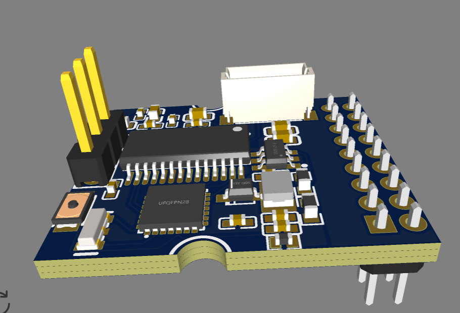
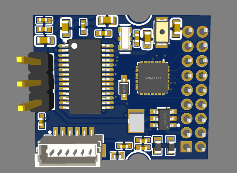
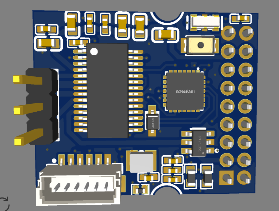
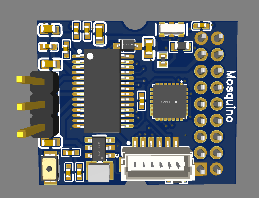
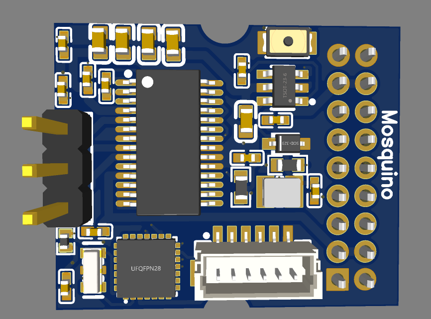
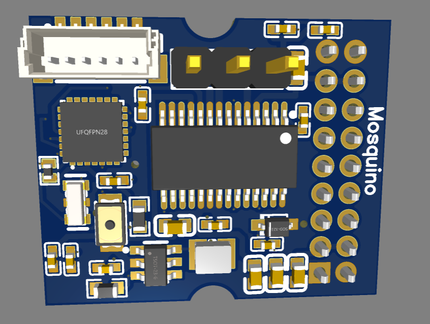
I had a better look at the board. You need to completely rearrange it. The mcu is too far from the crystal and decoupling capacitors. Please read documentation acout mcu layout.
Two sided board may be needed to fit what you want.

Cheers,
Valentine

1 Like

I’m down to 2 errors here

The oscillator seems OK though the traces are non symmetrical but the frequency is not too high so you will be fine. The buffer and decoupling capacitors are still too far. They need not only need to be physically next to the pins they decouple MCU but to be connected with direct traces.

Please see the Mosquito board the way it’s done.

Cheers,
Valentine

1 Like

Is this version 2.2 slightly more sensible?


2.2

Just four errors I can’t work out currently. I need to beef up some of the power and motor traces

Yes. I do have comments but at that level it may work.

Once you are done let me know I’ll check again.

Valentine

I have a couple of errors left in 2.2, but suspect I may have to move things around anyway if you are able to give a bit more feedback