I am currently tuning my motor for closed-loop velocity control but I am having some issues that I am not how to fix them. I am using a GM3506 w/ AS5048A encoder (using Magneticsensor PWM). The issue I am having it seems like at low speeds < 5 rad/s it is vibrating a decent amount and seems somewhat jittery still. I have played with the tuning parameters and below is the code I am currently using:
const int MOT0_PhA = PB1;

const int MOT0_PhB = PB0;

const int MOT0_PhC = PA7;

//Encoder Pins PWM

const int ENC1 = PC0;

const int ENC2 = PC1;

const int ENABLE_PIN = PA4;

//Poles of motor

const int pole_pair = 11;

// Setting up sensors

//MagneticSensorAnalog sensor = MagneticSensorAnalog(PC0, 5, 935);

MagneticSensorPWM sensor = MagneticSensorPWM(PC0, 4, 938);

void doPWM(){sensor.handlePWM();};

BLDCDriver3PWM driver = BLDCDriver3PWM(MOT0_PhA, MOT0_PhB, MOT0_PhC, ENABLE_PIN);

// Motor init

BLDCMotor motor = BLDCMotor(pole_pair, 5.57);

// For live tuning

float target = 0.0;

void serialLoop() {

  static String received_chars;

  while (Serial.available()) {

    char inChar = (char) Serial.read();

    received_chars += inChar;

    if (inChar == '\n') {

      target = received_chars.toFloat();

      Serial.print("Target: "); Serial.println(target);

      received_chars = "";

    }

  }

}

void setup() {

  // monitoring port

  Serial.begin(115200);

  // initialise magnetic sensor hardware

  sensor.init();

  sensor.enableInterrupt(doPWM);

  motor.linkSensor(&sensor);

  // driver config

  driver.voltage_power_supply = 12;

  driver.init();

  motor.linkDriver(&driver);

  //limiting motor movements

  motor.voltage_limit = 12;

  motor.velocity_limit =  80;

  // set motion control loop to be used

  motor.controller = MotionControlType::velocity;

  // controller configuration

  // default parameters in defaults.h

  // controller configuration based on the control type

  // velocity PID controller parameters

  // default P=0.5 I = 10 D =0

  motor.PID_velocity.P = 1;

  motor.PID_velocity.I = 10;

  motor.PID_velocity.D = 0.0001;

  motor.LPF_velocity.Tf = 0.5;

  // jerk control using voltage voltage ramp

  // default value is 300 volts per sec  ~ 0.3V per millisecond

  motor.PID_velocity.output_ramp = 1000;

  // since the phase resistance is provided we set the current limit not voltage

  // default 0.2

  motor.current_limit = 0.5; // Amps

  // use monitoring with serial

  Serial.begin(115200);

  // comment out if not needed

  motor.useMonitoring(Serial);

  // initialize motor

  motor.init();

  // align sensor and start FOC

  motor.initFOC();

  Serial.println("Motor ready.");

  _delay(1000);

}

// velocity set point variable

float target_velocity = 1.0; // Rad/s

void loop() {

  serialLoop();

  // main FOC algorithm function

  motor.loopFOC();

  motor.move(target);

  motor.monitor();

}
I am using the serial window to change the speed and below is a snippet of the target velocity (lefts most column) and the measured velocity (3rd column).
The measured velocity seems pretty unstable and I think that is what is causing the issue but not sure whether its the PID tuning or maybe the accuracy of PWM. Open to any suggestions or questions you may have!
I may need to if I know there isnt any other way I can improve it at the moment. The only issue is the current sensor I purchased only has the PWM wiring and I would need to buy the other one to use SPI. Does using SPI actually improve the smoothness movement in the motor due to better accuracy?
PWM sensor type is arguably the worst performing type of sensors for the simplefoc. One of the reasons why is that we use function micros() to measure the duration of the pulses. As these pulses have the duration of arround 1ms (1kHz), the best resolution you can hope for is 1000 cpr. Which is really low/.
When it comes to slow movements, the resolution of the sensor plays a great role, basically the more precise the sensor the lower the velocities you will be able to run your motor with.
So there is couple of thins you can try:
Try finding better pid parameters. Try using the Commander interface and the SimpleFOCStudio
Try to implement better code for the PWM sensor, if you are experienced with embedded programming this should not be too complicated. The implementation should be much more hardware specific than the one we provided.
Try adding a bit of angle filtering: try changing motor.LPF_angle.Tf.
If nothing of all these things work, you will probably need to change the sensor
I appreciate the response! Yea based on what I have been reading it does seem like PWM is not the best option to go with in terms of precision…
I will continue to try and tune the PID parameters some more but if that does not work out maybe ill take a stab at implementing some better code. I did try the filtering which helped a bit but still not achieving the smoothness I am looking for at low speeds.
Worse comes to worse may have to find the SPI version of my sensor (Not sure why its difficult to find one with the SPI wringing on it, they only seem to sell the PWM version).
Just as an aside, you can order the AS5048A from AMS - the small evaluation board it comes with standard 2.54mm pitch holes you can easily solder wires or a header to:
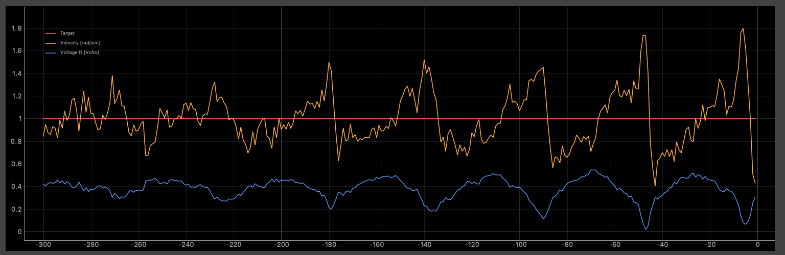
I’m finding my velocity output is somewhat unsmooth even with SPI communication:
Oh there we go good find! Only downside is I would would probably have to redesign the “backpack” that holds the current sensor in nicely so may make the whole assembly a bit beefier.
Interesting, based on the looks I would have to say it looks about the same as mine (didnt actually plot it but the spread in values seems similar). Was this using the monitoring software?
@DGAQ you cal also try downsampling the motion control loop. It will take a bit more time in between velocity calculations and the filtering will work better. motor.motion_downsample = 5; // downsample 5 times
He has implemented this sensor “properly”, exploiting all the hardware features of the stm32.
Now regarding the smoothness that you can expect.
With the PWM sensor the highest resolution you can reach is 4096 cpr. And that is really not a lot.
For 1 rad/s velocity you will be passing through ~650 cunts per second and if your loop runs at 1khz then you’ll see 1 count change in each 2 loop calls
Which makes for a terrible velocity calculation.
So what you can try to do is leave the FOC loop running at max frequency and calculate the ;motion control loop down-sampled to 5ms per call for example. This you can do with the motion_downsample parameter. At the moment this parameter is a ratio not the time so seting it to 10 means that your motor.move() will be called each tenth time the motor.loopFOC() is called.
Also I have a question, does your motor move smoother in torque mode?
That’s our new SimpleFOCStudio, thanks to @JorgeMaker
Give it a shot, its handy for this kind of thing, but of course the monitoring output will also affect performance a little bit.
I have to say I’m puzzling about this, because the angle output is so smooth, but the velocity output just isn’t. It’s smooth enough that velocity mode works, and like Antun said, you can smooth it more with the downsample and the Velocity-LPF, but I have the feeling that it should be smoother, and there is something I’m still missing. I wonder if there is discretisation on the timer side, which paired with the loop frequency used leads to this oscillating output on the velocity… or if it is actually caused by the interaction of the sensor lag and the PID controlling the velocity around the set-point.
@Antun_Skuric I see that motion_downsample but did I did read about it and saw that it could help with the overall smoothness. Was just too deep into tuning the PID I didnt end up trying it out.
The post that you linked looks promising based on the the statistics test results he had. I do wonder if he had tried using that in velocity mode or if that’s just the raw output of the sensors?
And when you say run it at the max frequency do you mean adjusting the BLDC driver frequency? On the docs I did find driver.pwm_frequency = 50000; and for the STM32 you can max it out to 100kHz.
Lastly, I have not tried running it in torque mode yet mainly since I took a deep dive into the velocity mode but I will try this also. Wish I had more time to test out all the suggestions so sorry for the delay but will share my findings when I get a chance
ahhhh so it is that I was wondering. I am also a little confused because in angle mode I have had the same smoothness but assumed that velocity would be similar. Do you think that the thread @Antun_Skuric pointed me to about the improved STM chip code with PWM sensors may help?
Like I said above thank you all for your help! I wish I had more time to test and try out your suggestions but as soon as I try I will let you know my findings.
It will definately improve the accuracy of the PWM measurements, which as Antun pointed out are not as precise to begin with. On the PWM you get 12bit, vs 14 on SPI… I haven’t done it myself though, so I can’t give you a experience-based answer, I’m sorry…