storm32_bgc v1.31
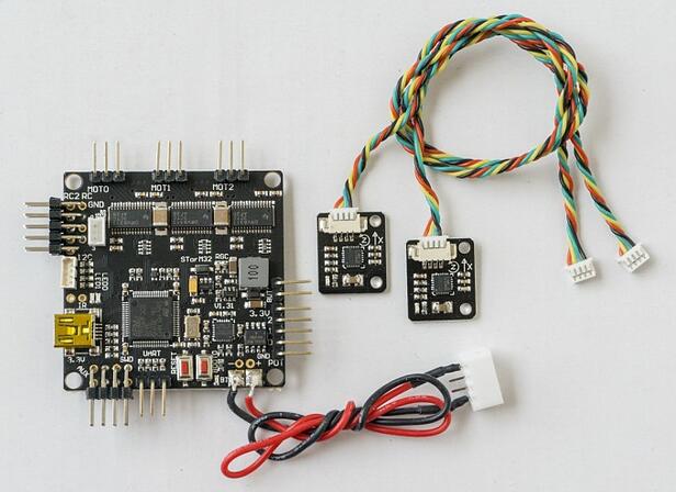
1. Hardware
STorM32 V1.31 --www.olliw.eu
The red font is a hardware change


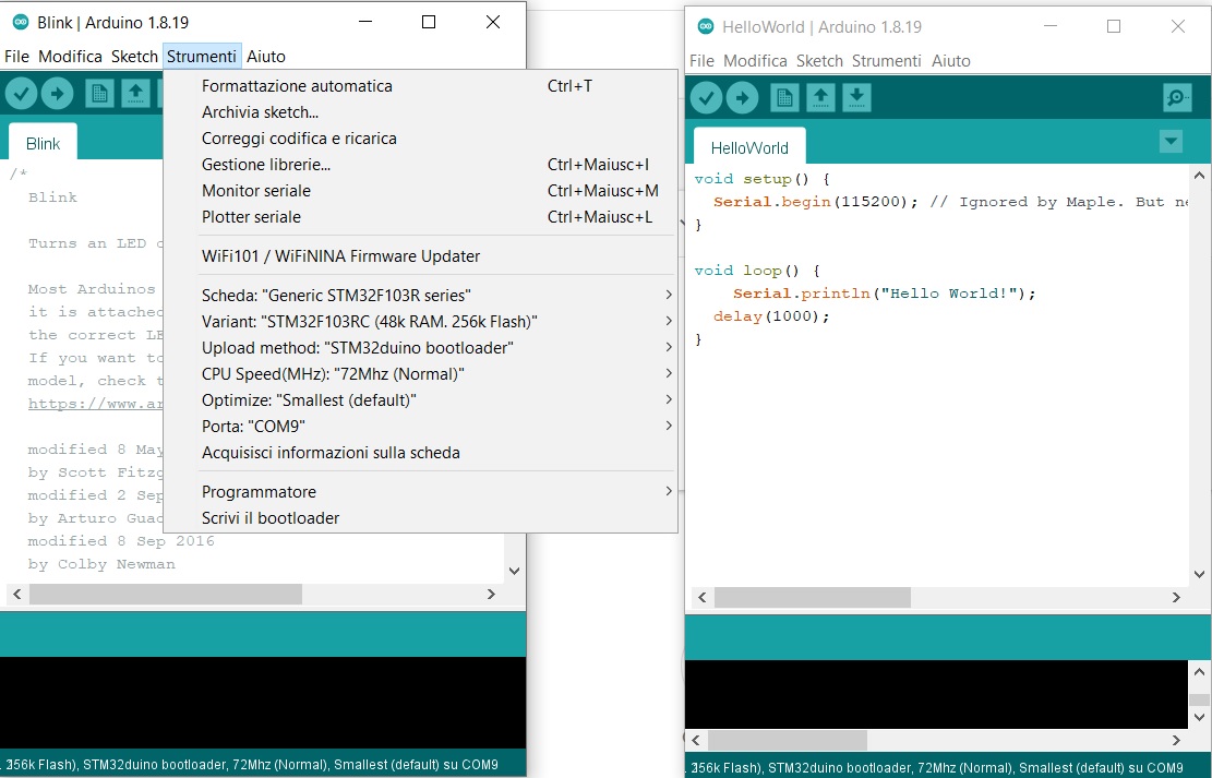
2. Bootloader
uses bootloader of “stm32duino” – “Generic STM32F103R Series”
-–>GitHub - rogerclarkmelbourne/Arduino_STM32: Arduino STM32. Hardware files to support STM32 boards, on Arduino IDE 1.8.x including LeafLabs Maple and other generic STM32F103 boards
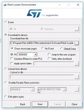
St official flasher tool
Used to refresh binary files - https://www.st.com/en/development-tools/flasher-stm32.html
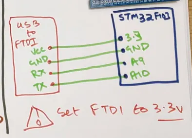
PA9---- STorM32 V1.3 JP7 -RC1
PA10 — STorM32 V1.3 JP7- RC0
Note: refresh binary files —Connect boot0 to VCC (1) The boot0 is (STorM32 V1.3)’s SW2, When you use flash loader, you need to press SW2!
3. Changes of SPI in simplefoc
3.1: MagneticSensor.cpp Add the following lines
#include <SPI.h>
#define SPI1_NSS_PIN PA4    //SPI_1 Chip Select pin is PA4. You can change it to the STM32 pin you want.
#define SPI2_NSS_PIN PB12   //SPI_2 Chip Select pin is PB12. You can change it to the STM32 pin you want.
SPIClass SPI_2(2); //Create
3.2: MagneticSensor.cpp All of them: SPI.XXXX Statement, change to SPI_ 2.XXXXX
For example: SPI.begin () Change to SPI_ 2.begin();
4. About motor driver chip drv8313
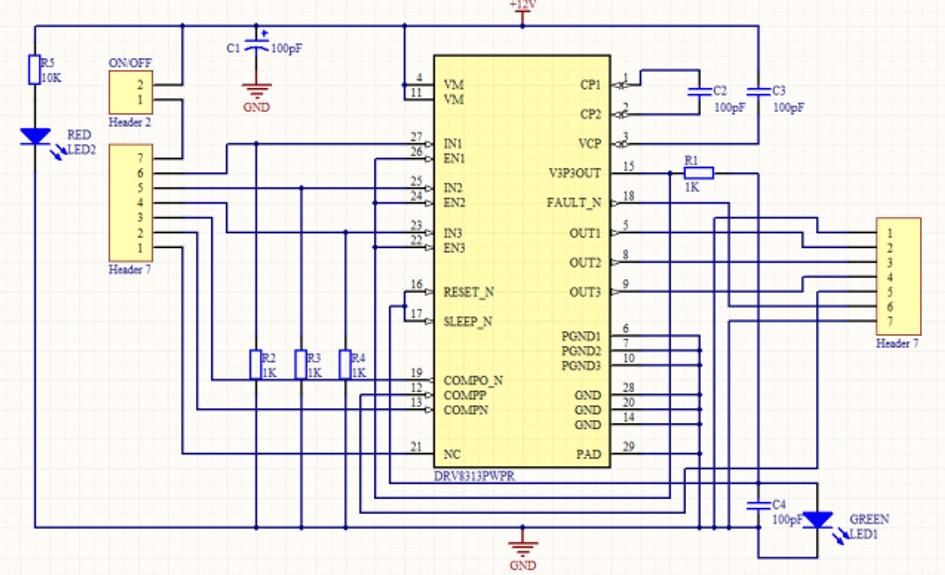
4.1: EN of drv8313_ The pin is directly connected to its own 3.3V, so when we use simplefoc, we set en_ When pin is used, only one idle pin needs to be found and no actual operation is needed
4.2: So, when you want to pass en_ When the pin turns off the motor, it is invalid. You can only let PWM be zero, which means the motor is turned off!
5. my test Code:
//STORM32 BGC Board V1.31 -->MCU == STM32F103RCT6 (48K RAM,256K Flash)
//                        -->MOTO Driver IC == Ti DRV8313
//Bootload: used STM32duino "Generic STM32F103R Series"
//Hardware change:Undo LED0 & LED1, release PB12, PB13.
//Software migration: https://github.com/askuric/Arduino-FOC

#include <SimpleFOC.h>

// External Encoder AS5048A/////////////////
#define ENC_SPI_MISO PB14  // AUX0 = D33
#define ENC_SPI_MOSI PB15  // AUX1 = D34
#define ENC_SPI_SCK  PB13  // LED1 pin =D32
#define ENC_NSS      PB12    // LED0 PB12 = D31
// MagneticSensor(int cs, float _cpr, int _angle_register)
//  cs              - SPI chip select pin
//  _cpr            - counts per revolution
// _angle_register  - (optional) angle read register - default 0x3FFF
MagneticSensor AS5x4x = MagneticSensor(ENC_NSS, 16384, 0x3FFF);

//moto 12N14P size:4108 KV=66 (used storm32 BGC's MOTO0-PB1,PB0,PA7-->TIMER3-CH4,CH3,CH2)
const int MOTO_PhA_pin = PB1;  // A: PB1=D28
const int MOTO_PhB_pin = PB0;  // B: PB1=D27
const int MOTO_PhC_pin = PA7;  // C: PA7=D11
const int MOTO_EN_pin  = PA4;  // moto enable pin PA4=D10
const int num_pole_pair = 14;  // pole pair number

//  BLDCMotor( int phA, int phB, int phC, int pp, int en)
BLDCMotor motor = BLDCMotor(MOTO_PhA_pin , MOTO_PhB_pin , MOTO_PhC_pin ,num_pole_pair , MOTO_EN_pin);

//gets the target value from the user,when Test Moto velocity.
// velocity set point variable

float target_velocity = 0;
unsigned long  t = 0;
long timestamp = _micros();

void setup() {

   // debugging port:maple's DFU/Serial port
  Serial.begin(115200);
 // while (!Serial);
  _delay(100);
  Serial.println("serial ready.");

  // initialise magnetic sensor hardware
  AS5x4x.init();

 // power supply voltage
 // default 12V
  motor.voltage_power_supply = 12;

  // choose FOC algorithm to be used:
  // FOCModulationType::SinePWM  (default)
  // FOCModulationType::SpaceVectorPWM
  motor.foc_modulation = FOCModulationType::SpaceVectorPWM;

  // set control loop type to be used
  // ControlType::voltage
  // ControlType::velocity
  // ControlType::angle
  motor.controller = ControlType::velocity;

  // contoller configuration based on the controll type
  // velocity PI controller parameters
  // default P=0.5 I = 10
  motor.PI_velocity.P = 0.2;
  motor.PI_velocity.I = 20;
  // default voltage_power_supply/2
  motor.PI_velocity.voltage_limit = 6;
  // jerk control using voltage voltage ramp
  // default value is 300 volts per sec  ~ 0.3V per millisecond
  motor.PI_velocity.voltage_ramp = 1000;

  // velocity low pass filtering
  // default 5ms - try different values to see what is the best.
  // the lower the less filtered
  motor.LPF_velocity.Tf = 0.01;

  // use debugging with serial for motor init
  // comment out if not needed
  motor.useDebugging(Serial);

  // link the motor to the sensor
  motor.linkSensor(&AS5x4x);

  // initialize motor
  motor.init();
  // align sensor and start FOC
  motor.initFOC();

  Serial.println("Motor ready.");
  Serial.println("Set the target velocity using Serial windows");
  _delay(1000);
}
unsigned long Now;
unsigned long delta=0,sum=0;
long loop_count = 0;

void loop() {
  // iterative state calculation calculating angle
  // and setting FOC phase voltage
  // the faster you run this function the better
  // in arduino loop it should have ~1kHz
  // the best would be to be in ~10kHz range
  static String inputString;

  Now =  _micros();
  motor.loopFOC();
  delta =  _micros() -  Now;
  sum = sum + delta;
  if (loop_count++ > 1000) {
    Serial.print("LoopFOC Time (Dec)  :");
    Serial.println(sum/1000);
    loop_count=0;sum=0;
   }

  // iterative function setting the outter loop target
  // velocity, position or voltage
  // this function can be run at much lower frequency than loopFOC function
  // it can go as low as ~50Hz
  motor.move(target_velocity);

  // function intended to be used with serial plotter to monitor motor variables
  // significantly slowing the execution down!!!!
  // motor.monitor();


  if (Serial.available()) {
    // get the new byte:
    char inChar = (char)Serial.read();
    // add it to the inputString:
    inputString += inChar;
    // if the incoming character is a newline
    // end of input
		if (inChar == '\n') {
		target_velocity = inputString.toFloat();
		Serial.print("target_velocity: ");
		Serial.println(target_velocity);
		inputString = "";
		}
	}

  }
6. Hardware specific library modifications
6.1 PWM, DELAY…modify (The destination file is located in FOCutils.cpp )
void setPwmFrequency(int pin) {

    if (pin >= BOARD_NR_GPIO_PINS) {
		//Serial.begin(115200);
	  	//_delay(100);
        Serial.println("DEBUG: Set high frequency PWM.PIN Was wrong!!");
     }
	pinMode(pin, PWM);
	uint16_t ducty_Num_Max = 72000000/36000;

	timer_dev *dev = PIN_MAP[pin].timer_device;
	uint8_t cc_channel = PIN_MAP[pin].timer_channel;

	timer_pause(dev);
	ASSERT(dev && cc_channel);
	(dev->regs).bas->ARR = ducty_Num_Max;
	timer_resume(dev);
	timer_generate_update(dev);
}


// function buffering delay()
// arduino function doesn't work well with interrupts
void _delay(unsigned long ms){
  long t = _micros();
  while((_micros() - t)/1000 < ms){};
}


// function buffering _micros()
// arduino function doesn't work well with interrupts
unsigned long _micros(){

		return (micros());
}
6.2 setpwm() modify!(The destination file is located in BLDCMotor.cpp )
// Set voltage to the pwm pin
// - function a bit optimized to get better performance
void BLDCMotor::setPwm(int pinPwm, float U) {
  // max value
  float U_max = voltage_power_supply;
  uint16_t Max_ducty = 72000000/36000;  //72M主频除以PWM的频率,即为占空比最大细分度.
  // sets the voltage [0,12V(U_max)] to pwm [0,Max_ducty]
  // - U_max you can set in header file - default 12V
  int U_pwm = Max_ducty * U / U_max;

  // limit the values between 0 and Max_ducty
  U_pwm = (U_pwm < 0) ? 0 : (U_pwm >= Max_ducty) ? Max_ducty : U_pwm;
  U_pwm = U_pwm +0.5; //取整

  timer_dev *dev = PIN_MAP[pinPwm].timer_device;
  uint8_t cc_channel = PIN_MAP[pinPwm].timer_channel;
  ASSERT(dev && cc_channel);
  // CCR1的预加载寄存器使能,每次更新事件发生后才更新占空比
     __IO uint32 *ccr = &(dev->regs).gen->CCR1 + ( cc_channel - 1);
    *ccr = U_pwm;
    *bb_perip(&(dev->regs).bas->CR1, TIMER_CR1_CEN_BIT) = 1;
}