Hello everyone! This is my first post here and YouTube has led me to this awesome community. I’ve been reading posts and many are geared towards making smaller solutions or compaction. My needs are a bit different, however. I have an Axial Flux motor that I designed and it is my small scale prototype. I intend to feed it 30v at 15A (max current not continuous). The purpose is to be able to produce the torque figures I have in mind as well as be able to have nice closed-loop control for RPM settings.
Any help? Also, I can answer any questions if more info is needed.
Welcome to the forum. We hope you find what you need.
Let’s see if anyone else answers first. If no one is willing to step up I may be able to offer some help.
Meanwhile, could you please provide us with more information about your project, else you won’t find much help with the limited information you gave. Any pictures/videos of your prototype would be helpful, if possible. Drawings, numbers, use cases, etcetera.
Last but not the least, are you looking for open, free help or you are willing to monetary support the development help?
This is a 3 phase Axial Flux Motor. I would like to use an encoder on one of the output shafts (it has two, one on either end) to send data to a controller as well. It’s use case right now is purely proof of concept. This is my first in-house designed motor and I’m trying my best to eliminate variables such as control issues or solutions. This more will be run for mostly torque figure testing as well as efficiency to test the effectiveness of my construction methods. it is made from PLA+ plastic so it’s not fit for “proper” use. In terms of if I am willing to compensate someone monetarily, on this one I am more so looking for guidance to be pointed in the direction of being able to supply the 450w of power I will need through the FETs. I noticed many times on high power loads that many mosfets will be used but I am having trouble understanding how to properly drive all of these and integrate the FOC library. I can certainly design the PCB, but I do need some help getting there. In terms of the full scale model which is a high HP axial flux, that one I will be consulting a few people for.
I’ve attached a couple of images of the coreless motor design. It’s nothing new but it’s mine.
Thank you. To put things in a bit more ordered fashion, please confirm my understanding:
Help with sensoring the above design. This means advice or mechanicals, sensors, connection, protocol, etcetera.
Your design will deliver 15A / 30V maximum stall torque, therefore you will need advice on a combination of MCU / Driver or complete integrated solution off the shelf.
You are also open to designing your own PCB from scratch, do I understand correctly, if off-the-shelf solution is not available?
You need help with integrating the MCU / Driver with the prototype motor, both electrically and mechanically, as well as programmatic help with making it spin, control the torque, velocity and angle.
You are willing / able to monetarily support the effort to some degree.
You already have people that will consult with the final design of the high power axial flux motor.
Very thorough response, I will answer each question.
I have the mechanical portion taken care of in terms of adding an encoder, it is not shown in the image. My apologies.
Preferably something not off of the shelf. The need to learn these systems myself is high as I would rather learn and make my own specifically tailored to my needs. Whether this is a combo like you speak of or possibly even something else open source. A lot of off the shelf products exist that could fill my power need, but where’s the fun in that
Designing a custom PCB is the goal. I have some experience creating smaller, more simple PCB’s but nothing capable of moving this amount of power or much to do with BLDC technology.
Programmatic help is in the air. I am rather decent at that so long as documentation is good which I assume it is, however I’m sure I’d have questions here or there. As for the MCU/Driver integration in terms of electrical means, that is an area of weakness for me where I simply lack the experience.
5/6. I am certainly willing to provide monetary compensation for full-fledged help. What that number is at this moment, I am unsure as I do not know how to put a price on something that abstract. I would much prefer somewhat more if I could be guided towards either anything obvious I am overstepping or possibly towards literature, open source resources, or demos. I am open to a lot depending on what is being offered. Now since this is scale prototype motor, the purpose is keeping it’s R&D cost as cheap as possible. The full scale high HP model however, not so much. That is for another time, however.
Thank you. Let’s first wait and see if anyone is willing to help you. As I said, I might be able to help but you may not like my offer. Give it a few days.
Meanwhile please read other threads, there is a lot of information, discussions, pictures and schematics of PCBs on this board. You may learn a lot.
Your Axial Flux motor is a 3-phase design, so as I understand it you should be able to drive it directly with SimpleFOC, as if it were a normal BLDC motor…
So you need a driver architecture - 30V, 15A is quite a lot, but within range for many FETs. You should have no problem finding some that suit your needs, despite the global semiconductor shortage…
For testing it out, you might want to consider a finished motor driver, ST-Micro and TI have some higher powered models which could work if they’re in stock. Something like this:
For prototyping, you could use an external MCU board, like a STM32 Nucleo, Adafruit Metro M4 or ESP32 DevKit - that way you don’t have to worry about finding an available MCU for the moment.
I would not try to double up the FETs, personally. Switching FETs in parallel can be tricky, if they don’t switch at the same time, a single FET carries the load for some amount of time, which can be problematic. You could just ignore this, and hope for the best (one school of thought), or (my preference) stay away from this extra complexity in the first place, since parallel FETs aren’t really needed for 15A.
For 30V you’ll probably need a configuration with 2 N-Channel FETs to make each half-bridge, and you’ll need dual N-channel drivers for each half-bridge. The tricky part here is that this needs a charge pump, because the high-side N-channel FET needs to be switched on with a voltage greater than supply voltage (so maybe 35V for the 30V supply). It is simplest if you can find a 3-phase driver IC (or 3 single channel half-bridge drivers) which integrate the charge pump.
I cant see why he should not do parralleling. If the on_time is low and the design is good (no weird difference in trace to gate). The Likelyhood of that sort of missfire will definitely decrease. The gained cooling surface will double.
If he is not constrained for space and money, paralleling is an inferior option to the really cheap high voltage / high current mosfets, such as this 40V / 123A mosfet
My assumption is that this is a DIY educational proof of concept design, and not something @VFM wants to productize and sell. Cheap, in stock discrete components on a breadboard is all he (she?) needs.
Let’s wait and see if @vfm will give us more details.
As Valentine said, yes this is an educational proof not fit for production. I physically have no size constraint what so ever. Component cost is not much of a big deal either. I had planned on using my Nucleo for logic as someone above mentioned.
Also to answer a question about why I wanted to do parallel switching for the fets, it’s because the next step up from this motor is a high HP CNC milled motor that will require parallel switching as no Fet on the market that I’m aware of can move that voltage and amp load with a acceptable switching rate. The Tesla inverter is comprised of 26 fets, just for example.
The reason I am chasing something like this rather than getting an off the shelf traction inverter is because I do not need just about any of the features they have. My load can be driven in two directions but I do not need functions such as torque splitting, traction control, temp limiting, etc. as such I would prefer to not have to buy a $10k traction inverter when I can spend a tenth of that on a much more simple version that I make my self.
The High HP model will be a 400v 540A (stall) Axial flux. The amperage may be slightly off but it’s 300HP converted right about. The High amps shown will only be hit EXTREMELY momentarily as this is driving a boat propeller believe it or not. It’s likely it may not even ever hit it as at no point should a prop in water give the resistance of a tire on asphalt.
As for switching rates(?) I am not quite sure what I’ll actually need at the moment. I am going off of the guidance of someone else that explained that the incredibly high load fets had somewhat crappy switching rates but that could very well be conjecture.
I migrated here after being on an EV forum for a few months and didn’t really make it too far as on that side it seemed people were less for making components and much more for making their actual builds which is understandable.
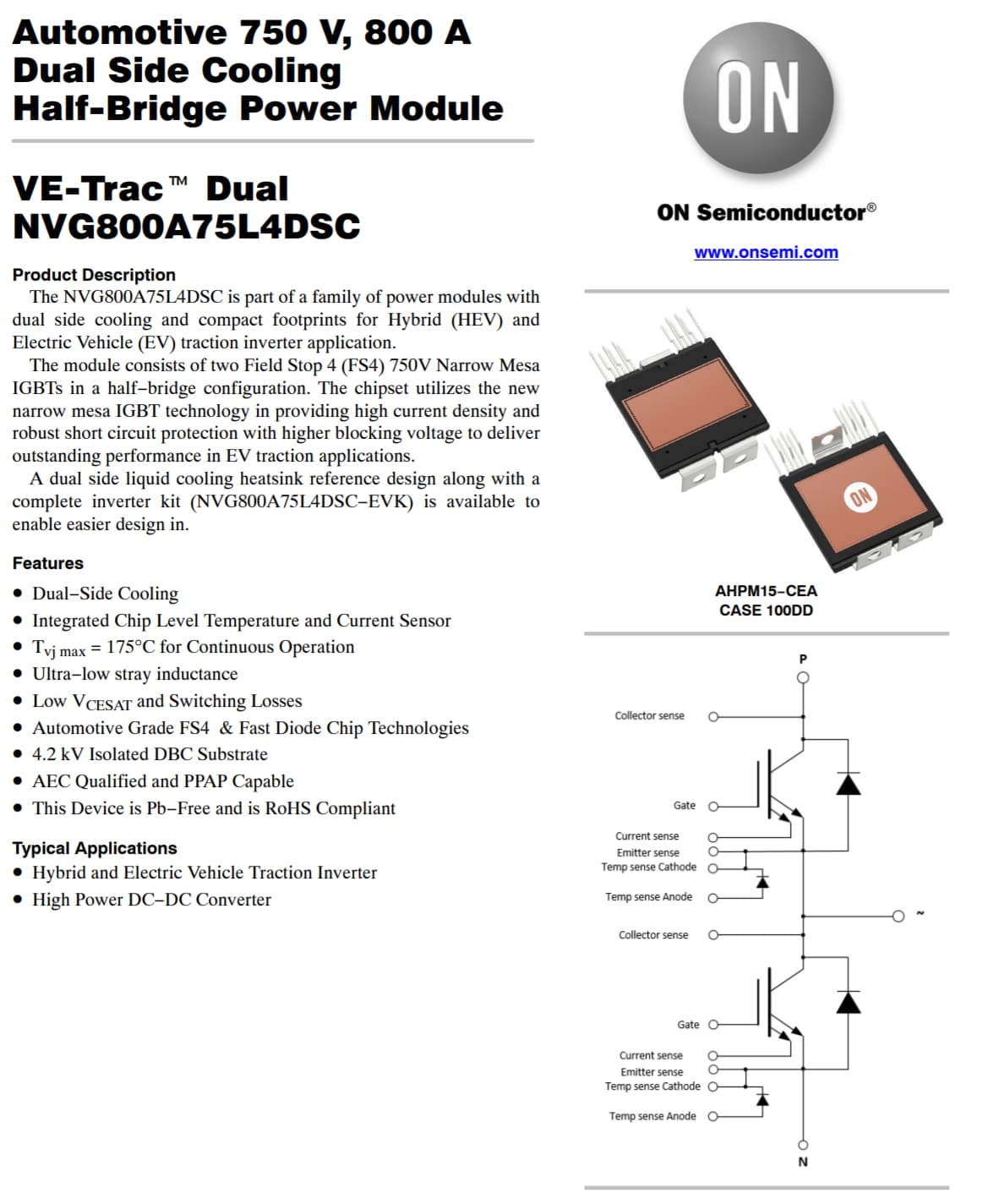
Oh, I see. I thought you are going into 4000V / 3000A region, where you really need IGBTs and to double them. You have absolutely no problem then finding discrete off-shelf MOSFETs for 500A. May not need to go IGBT or double them. These MOSFETs are stocked. A little bit expensive but no problem. Let me know if you need the part numbers.
Any way I would go IGBT instead of MOSFET because high voltage/high power MOSFETs are very hard to find these days.
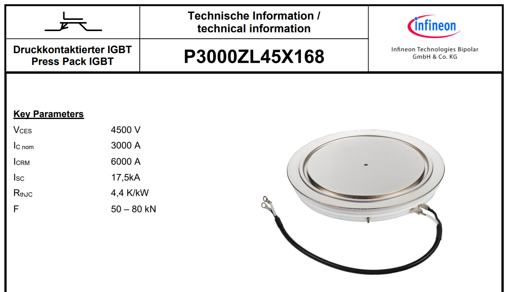
Here, check out the IGBT modules. That’s high power.
Wow, I love the headroom that provides for me as well for expanding into higher Hp options. Seeing as this is half bridge, I would need 3 of these modules?
Also, do you know of any resources where I can get into properly designing controllers? Even if that means starting with something quite low power. I’ve been scouring the forum and I can see peoples designs but without schematics it can become a bit lost on me as to why specific components are used and how. For example, that 30A model you made with the component placement on the right side of the board is something I have never ever seen before.
I can read data sheets and am more than eager to learn. If there are any posts I may have missed that really dive in to what that person is doing/making, that would be awesome to be linked!
Unfortunately, no, short of getting a college/university degree in Electrical and Power Engineering, or spending a few years full time learning by trial and error. Best way is ask someone to do it for you.
That’s because this is original design.
Not really sure those posts exist. There were a few threads about IGBT boards, you may want to search for IGBT on the forum search feature. However, you will not find a step by step instructions or guidelines, because people already knew how to design these.
Wish there was something else we could do. As I said, may be someone else would be willing to help. Unfortunately, this is so niche and specific, that these skills are very expensive and people won’t do it for free.
May be others could give you a different answer, I don’t know. As I said, I could help you but you won’t like it.
Cheers,
Valentine
PS You can always take those ready open designs and order a couple boards yourself, it will cost you very little, but this would be using my designs, and you want your own original design. May be this is another way for you to check your idea, who cares whose design board you used for proofing the concept?
That is extremely fair. I may very well be able to secure the funding to warrant me being able to commission the design. The 300HP model is going to require a good bit more than my knowledge when it comes to the controller side of things and I am certainly willing to ask for that help and compensate it once development is at that stage. For now, I need to focus on proving my concept motor in its small scale where quite honestly at this point, I couldn’t care where the board comes from so long as it works and I can understand what is going on. Also, thinking about it, if I commission the traction inverter electrical design, I do not seriously need to worry about making a controller from scratch at this time then.
Also, I will work to incorporate halls into my design. I feel I don’t need the granularity an encoder offers more than likely.
I’m one of those people who would disagree for the type of FETs / IGBT modules you’re looking at $10 for a proper encoder isn’t a lot. And having precise positions will enable more efficient control, reducing the power requirements for the same torque output…
Check out this app note, you might like it:
There are more app notes from TI, ST-Micro and Infineon, on choosing FETs, current sensing topologies and more.
The EBike/EScooter link I sent earlier also comes with complete schematics.
If you post schematics and questions here, I’m sure people will be more than happy to help! A 400V/540A driver will be a record for SimpleFOC, as far as I am aware. I look forward to seeing it! And the smaller one will also be interesting!