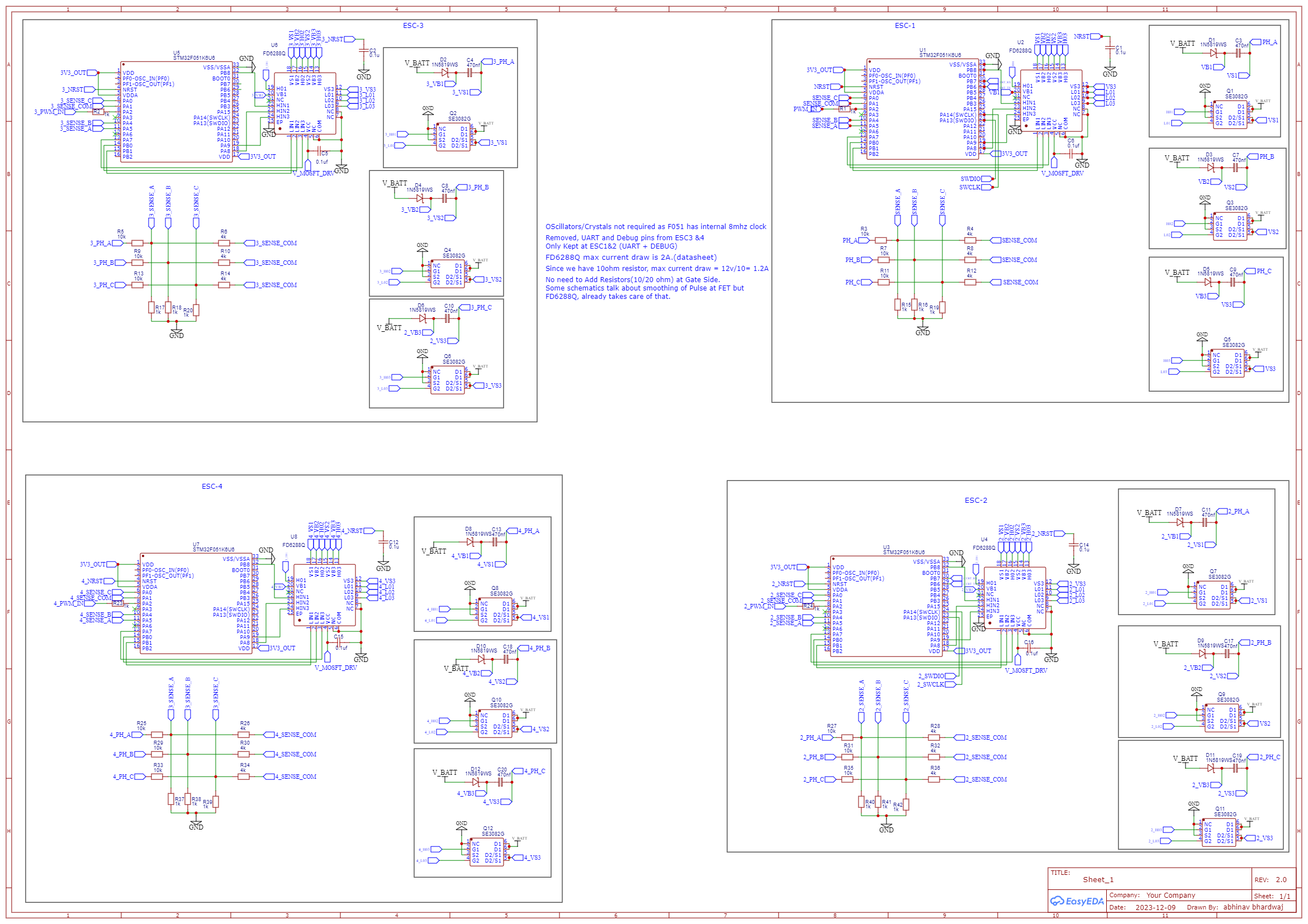
I am working on a 4 in 1 esc for my fpv.
Planning to power the Mosfet drivers directly from V_BATT (upto 5s battery) to avoid 12V regulator.
as @dekutree64 has suggested. will work upto 5S battery.
However i have a doubt where are the snubber circuits, RC pair between Source and Drain to tone down the spikes.
I think you will need a buck converter for anything over 3S, because the 3.3V regulator will produce a lot of heat. Either buck to 12V and regulate to 3.3V, or buck to 3.3V and run the drivers from V_BATT. And with a 4-in-1, you only need one buck converter to power all of them, so it won’t add much to the overall size and component count.

Looks good to me, but I’m no expert ![]()
You guys know we never figured out the noise issue on this board? I also have a bunch of them, if you want them I can mail them to you to experiment with.
@ Anthony_Douglas
Noise issues at which pint/port.!!! are these at phase 1/2/3 or A/B/C whatever you call them?
The input pins are unusable. Interrupts are triggered thousands of times per second from the noise alone. The uart is unusable.
Has anyone else seen that? I think a number of people have had the board made.
@Pete_Bowsers ?
I didnt end up getting any of the lepton V2, just the v3/QVADRANS, and I havent looked at how similar they are (also not sure what id be looking for). On the V3 Ive been able to use uart 1 & 3 without any issues if that helps at all (maybe also uart2? Dont remember if i tried). I also haven’t looked into using the inputs on it before, so no comments from me there either
I never had those issues, worked fine for me. If I remember, no one else was able to reproduce @Anthony_Douglas noise.
Valentine
Two people approached me to make boards for them, they were fine, no issues reported.
Cheers,
Valentine
It’s possible it was a manufacturing problem, I don’t want to rail on your design, I understand you did it for free, and it really helped the exploration process and was a good stepping stone, which has great value. But I got the exact same problem with 4 different boards in a batch of 20, haven’t even tried the others.
@Anthony_Douglas what are you doing with those input pins? I’ve made designs where I’ve marked pins as hall1,2,3 without providing pullups and those would behave the same as you describe (loads of phantom interiors) if external pullups weren’t provided. Internal pull-ups are usually far to weak, and providing external interrupts on board limits those pins usage for ‘unexpected stuff’.
Does uart work when motor is not running. It is quite hard to break uart at low speeds?
Anthony actually sent me a couple of boards from his batch.
I personally never really use hall sensors, I prefer the other sensor types. So I tested with a SPI sensor.
I had the board working, the motor was turning and both SPI and serial were working.
But I will say that it looked like the board was perhaps a little electrically noisy - I say this because the sensor values weren’t super-smooth, and the commutation was a little noisier (acoustically) than normally.
I did not investigate further because the memory limit of the MCU on those boards was reached by my test programs, and we sort of agreed it would need a version with a larger MCU or slight redesign anyway. At least that’s how I recall it now ![]()
And then Valentine designed the Quadrans with more flash memory and current sensing too…
So my result was that I could not duplicate the problems Anthony was experiencing here on my setup. Your explanation that the Hall Sensors need better interfacing is certainly a good possibility, I don’t know how Anthony had them set up.
Another thought I had is that also depending on motor and voltage levels used, the board might also benefit from some gate resistance and/or snubbing circuits. Being a simple small and cheap board these things were left off as non-essentials, but perhaps adding them will make things a little more “relaxed” electrically…
I’ve made a LeptonG4 version which is now finished and I will order and test it soon. On that version I include the footprints for gate resistors and snubbers so people can use them if they want.
I am trying to figure this out while solving few problems of my own.
-
I don’t see any Hall sensors in the schematics. Referring to Lepton v2 & lepton-g4 Designs(screenshot posted here
-
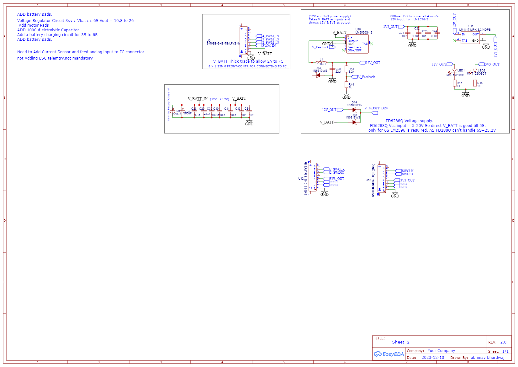
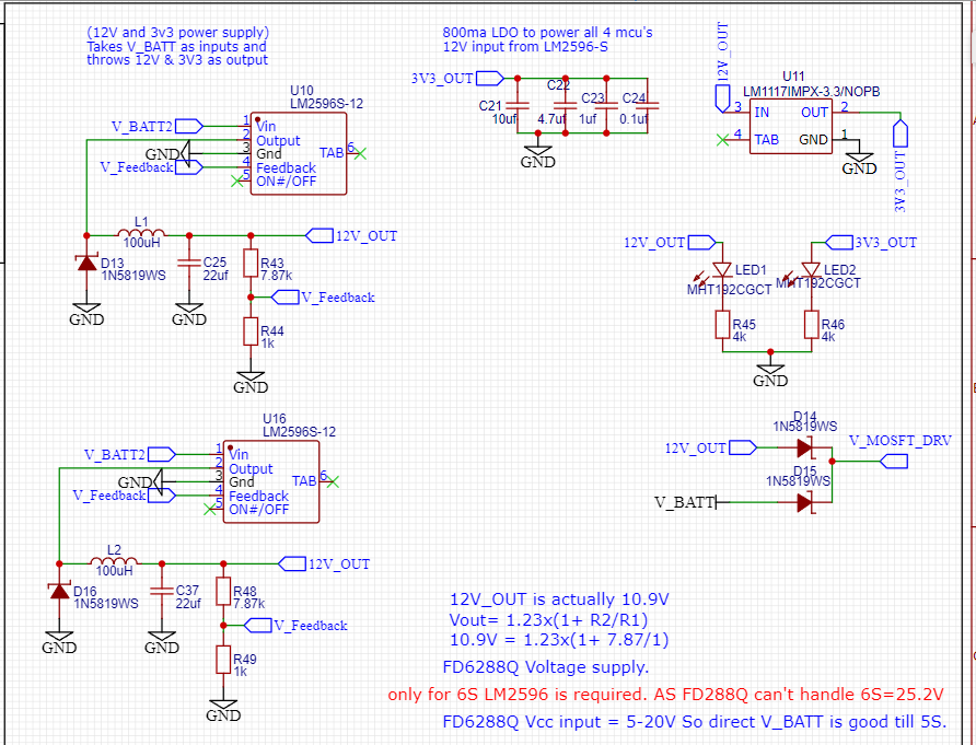
I want to run my circuit from 10.8V (3S Lipo) to 25.2V(6S). As there is 12V regulator (xl1509/ LMS2596). As soon as V_BATT will drop below 12V (which will pretty soon on 3S Battery).
12V Output will be unstable. How to tackle that!.
Also the V_BATT supply is this correct! or do I need this to be 12V.
Regarding snubbers is 470nf is good enough!! -
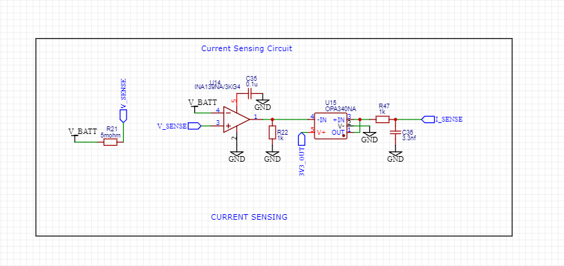
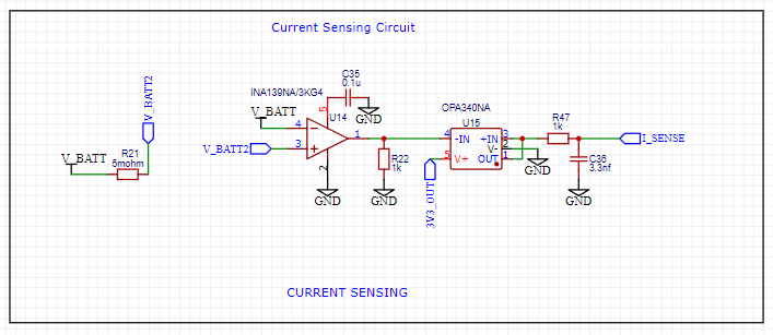
Regarding Current Sensor I didn’t find anything @runger Lepton-G4.
However I did this.

Hall Sensors use interrupts in SimpleFOC, we don’t have support for any UVW hardware drivers on any MCU types. So using interrupts, you can use any 3 interrupt-capable, input-capable IO pins. On STM32 MCUs, that is essentially any available IO pin.
So you can use the pins of the SPI interface, or any of the other pins…
Why do you need a 12V regulator? If you want your circuit to work from a 3S battery, then I would suggest using a voltage of 8V - this should be within range of even a very discharged 3S battery, so then you can use a normal buck converter or regulator to regulate the battery voltage to 8V.
8V should normally be enough as gate drive voltage.
However, a 6S battery with 25.2V - I would not design a regulator to drop this to 8V or 12V. It will be very inefficient and get very hot. Better to use a buck converter if you have such a wide input range.
If you really need to produce 12V from 3S-6S, then you can look at using a buck-boost converter or a SEPIC converter. These DC-DC converter types can produce a stable output voltage from an input that can be either higher (buck mode) or lower (boost mode) than the output.
Are these snubbers? It looks like the bootstrap capacitors?
Neither the Lepton nor the LeptonG4 designs have current sensing. For an example of a design with current sensing, please see Valentine’s “Quadrans” design…
I must admit I don’t understand your circuit. normally for current sensing you will need only the INA current sense amplifier. This chip is pre-configured for current sensing across a shunt resistor. The shunt resistor has to be in the current-path, i.e. the VBAT current flowing from the battery to the phases has to be passing through this resistor, and then you measure across this resistor with the INA amp’s IN+/IN-. It doesn’t look like that’s the case in your circuit?
It took me a long time to realize the Lepton 2.0 had noise issues, serial worked with a USB-TTL converter, but not with communicating with a Pico directly. There was a very high error rate. However I rarely got errors when typing or reading commands on my PC. There might be differences in flow control or something, I don’t know.
The noise was most noticeable with interrupts.
I did not use hall sensors, this stuff was all open loop. I never got past open loop with the Lepton, I moved to the B-G431b-ESC board. I can post the code, I think I already did somewhere, ti could be found in my post history.
I’m not harshing on the design, it’s a good form factor and would have been great for some things, I’m just trying to warn you.
I think the best hypothesis I came up with was: that it was ringing on the inputs to the mosfets. This caused very short high current drain as the mosfets turned on at slightly the wrong time. This caused noise on the power rails. I can’t get in there to modify anything unfortunately.