Lepton v2 revised design --- tested working 30V / 80A MOSFETs

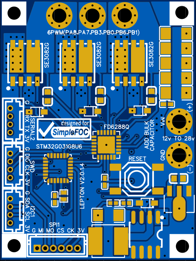
I’m opening a new thread, since the old one didn’t work out. This is a complete rework of my idea of an ultra-cheap SimpleFOC board. I tested it, it’s working. There is no current sensing, because at that low power you won’t really benefit from current sensing much.

Features:

30mm X 40mm

2-layer (!!!)

30V / 80A (170A peak) H-bridge integrated MOSFETs.

Fortior Driver

STM32G031 / 64MHz MCU

SPI, I2C, Serial and SDW pinouts

12V Buck

3V LDO

Less that $10 to manufacture including SMD and components !

I will post the schematics. This is a reference design, for those that are learning how to make SimpleFOC full-stack driver boards.

Please be extremely careful. This board is only for educational purposes. The 1oz copper will not carry more than 10A max if you are lucky, even though the MOSFETs are rated at 80A continuous. If you need more current you need to go for 2 oz copper, and 4-layer board, which means you will have to redesign the board by inserting extra copper layers, this will increase the current carrying capability to about 40A continuous (80A max pulse for a few milli-seconds) with good heatsinks and proper cooling. Also you MUST add an external 50V / 1000uF minimum bulk capacitor.

Enjoy and please ask questions.

Cheers,
Valentine


8 Likes

Instead of using the input power terminals, what if you left these areas on the back without solder mask and soldered the input wires all along the back of the board to provide high current capacity right to the MOSFETs?

Great idea. Yes, it will work. Anything goes. It will work just fine. And if you add 2oz 4-layers, and add more plates to the output, you can definitely pull about 50A with active cooling. That’s why I opened the design. Hopefully others will improve and test and share their ideas.

As I said I’m open to suggestions and can make those changes.

If I get the time I can add a crystal, if you notice the MCU is running on the internal RC oscillator without an external crystal, which is fine as long as you don’t need superior stability over a long period of time and no USB, which I did not expose anyways.

Cheers,
Valentine

Excellent! I wonder if we can pull a similar trick on the top side and flood the path from the MOSFET to motor wires with solder?

Yes, that could be done, however, I would add 4 layers and vias under the mosfets first which will be tricky because it will break the input voltage. However if we make islands instead of a continuous trace, the grease will isolate (insulate) the input voltage wires and will be able to manage the vias.

Again this is educational and very hobby/diy, I would not do that for a production board. Also soldering directly under the mosfet, you may overheat and melt the top layer and the mosfet will just plop out right off the board. So you need to use low-temperature bismuth solder for that on the bottom.

The bottom would look like that:

image

However 4 layer 2oz copper will not be cheap at all to manufacture!

If we pay for the 4 layers, then there’s no need for the input wire trick anyway.

Looking at a photo of the SE3082G’s underside, the solder pool should provide a good current boost by itself. That metal plate looks like it’s probably equal thickness all over, so only the pins are a pinch point. And there is a third sort of pin out the side that will contact the solder pool as well. EDIT: Running some calculations from the SE3082G datasheet dimensions, it looks like the two-and-a-half pins have a combined cross section of 0.2mm², which is about the same as the cross section of 1oz copper along two sides of the solder pad. So the solder pool should approximately double the current capacity.

And yes, I had been pondering how best to keep the MOSFETs in place while their solder is re-melted :slight_smile: Bismuth is an option, but also would be a risk of melting while running the motor.

I’m looking for a solution for making a very quiet fan, which reverses direction periodically. Conventional driver boards can’t reverse direction electronically, and also they tend to jump a lot when they start up.

I would like to combine a low cost, low current FOC board with a gimbal and some 3d printed components to make a complete ready to use servo motor solution. Stepper motors with a trinamic tmc2209 or similar driver are pretty good for low speed, you can get load detection and step loss detection (theoretically, I was never able to get the driver working so I couldn’t actually do that, though), but they don’t work for more than 10 rpm or so before they start making serious noise.

This is the only option for quiet motion at higher rpm, and might as well give it stepper motor like precision to make it more useful, since it doesn’t cost much.

But aren’t there chips that could reduce chip count? A chip that combines power mosfets and drive circuitry would make sense.

Also it’s not clear to me exactly how you use this thing. I would prefer to make a solution that accepted step and direction inputs, among any other options for input, so it is easy to use. Standard 200 steps per revolution with controllable microstepping. That would be the most modular, compatible solution. Higher level drivers that are already available etc. could be used relatively easily. If it had an angle sensor then of course closed loop would make sense. Also some feedback regarding how much load the motor is under and /or if it stalls is really important, IDK if we can get that here?

How much power you expect to draw ? What is your RPM range? There are wonderful chips specifically designed for fans, but they are pretty low current. They are fan-specialized chips. Why do you even want a stepper for a fan?

Also I’m confused, you say you want a quiet fan, then you say you want a complete ready to use servo motor solution? Which one is it?

Cheers,
Valentine

PS Please check out TI’s DRV10x series of fully integrated sensorless quiet fan controllers, up to 3A peak. I’m not sure how low RPM can they run a fan though.

Fantastic board!

I have a question about there being no USB chip on it - is it still possible to use Arduino’s serial plotter? I think I remember reading that the SWD port communicates to a virtual COM port using the STM32Programmer, is that correct?

Thanks!

1 Like

You are correct, however, since 1. I use a fully virtualized environment for my programming and 2. I do not need a virtual com port (and I don’t even know how to use it honestly) and 3. I have a serial probe I attach directly to my boards, there is not much I could contribute here. This is a full-blown SWD interface so if you know how to program it, the Serial must be no different than a Blue Pill for example. Try it on a blue pill and see if it works. STM32G031 is just another STM mcu. I may be able to fit a USB chip, however, it will make the board more expensive. I’ve done this with my other boards, but the chip and the USB connector are all extended components and also add to the board size.

You could also buy an FTDI converter, they sell them for a few bucks on Amazon.

https://www.amazon.com/HiLetgo-FT232RL-Converter-Adapter-Breakout/dp/B00IJXZQ7C

I replied to this by email but those replies rarely seem to make it through. What I seek is a general purpose solution, which is more valuable than a special purpose one. I could take an FOC chip and make a board from it and roll with that, however I hesitate to do that because it is not a contribution to the community much. It’s just treading water. I have to have a second look at the different options, it’s possible I should do that. However it might not cost much less, especially because I have to order the chips and board separately and solder them together manually, which takes substantial labor time.

I would much rather work on a general purpose solution that costs 30 percent more per unit in the end but has a broad range of uses.

Rpm range is probably 0-3000 or so rpm.

I will definitely check out the TI drv10x chips, thanks for the tip.

Hey - Amateurish question here, but is it right to think of Fortior chip being used as a Mosfet driver (stage 1) and the SE3082Gs as the output Mosfets (stage 2).

And if so, is this just because the STM does would burn out switching the output Mosfets at a fast enough rate?

Hi @slamjammin ,

Yes, the Fortior FD6288 is a 3-phase half-bridge driver, designed to drive 6 mosfets. And the SE3082G is a low voltage, mid power dual N-channel MOSFET, with the dual FETs internally connected in a half-bridge configuration.
And yes its like the first stage of switching and a second stage of switching.

It’s not so much to do with the rate, as with the drive capabilities of the MCU’s outputs. The MCU can safely drive about 20mA, and usually you don’t want it to source or sink that much current. But the FETs require quite a bit of charge to switch on, or need release quite a bit of charge to switch off, and so in order to have decent switching times, you have to pump enough current into them in a short time. This can be several 100mA or even a few amps of current.

So if you connected the FETs directly to the MCU, you would either burn up the MCU by drawing/sinking too much current, or you would have to increase the gate resistance on the path to the FETs to a level where the MCU is safe, but switch-on times are far too slow to be useful.

Also, MCUs operate at 3.3V (or some at 5V), and while this is enough to switch FETs in some scenarios, it isn’t suitable for this kind of FET and this configuration. FETs will switch more quickly when driven with higher voltages, and when using N-channel FETs on the high side of the half-bridge, you have to switch them at a voltage higher than VIN. Providing a voltage > VIN to the gates of the high side MOSFETs is another primary function of the driver chips. To do this, they integrate a “bootstrap circuit” which brings the high-side switching voltage to approximately VIN + VCC. On the Lepton, VIN is up to 30V, VCC is 12V, so the high side drive is up to 42V… if that 42V comes anywhere near a delicate MCU it will be toast.

Another reason to use a driver is that it offers a certain level of protection to the MCU against the high energy switching happening on the other side of the driver.
And finally the driver typically integrates a number of protections, like shoot-through protection, over-current protection, short-circuit protection and over-temperature protections. not sure which of these a Fortior chip has, but a good motor driver from ST-Micro or TI will have them all.

1 Like

Power MOSFETs require about 10v to 15v gate driving voltage to fully open and work at high efficiency. Also, even though the MOSFETs are voltage controlled, in order to deliver this voltage to the gate you need to charge the MOSFET gate with electrons (open the gate), so in a way you think of the MOSFET gate as a capacitor, you get that inrush of current to charge it and once charged, the gate stays open until you bring the charge down, in which moment the charge rushes back to the ground. So you need to:

  1. Source 12V to the gate, and depending on how big the MOSFET gate is, the charge is also big, and the inrush current will be big. For large MOSFETs you need to supply up to 10A current.
  2. Sink the charge back to close the gate and absorb 10A of current.

This is only instantaneous, however, pushing 10A of current back and forth, even for a few microseconds, will pretty much smoke any chip not explicitly built for that purpose. Hence, the need for the so called driver. Think of the driver as the spark plug in an ICE. To deliver that much charge, we use a charge capacitor. Think of the charge capacitor as the ignition coil in the ICE. Then you need to trigger the charge, which you do with the STM microprocessor, which you may think as the camshaft. So the camshaft start spinning, charging and discharging that capacitor into the gate, and opening and closing the gate.

To make the matters even more complex, the high gate, as @runger pointed out, must be opened with a charge which is 12V above the power voltage, so you must deliver 30 + 12V = 42V for the high gate to open, because the high gate is propped close with 30V pushing on it by the high voltage supply, so you need to overcome that voltage, then add another 12V to open the gate.

Now you see why you need a specialized chip to do that job. Pushing 42V x 10A = 420Watt. There is no MCU that could deliver 420 Watts of power. That’s of course for high end drivers and MOSFETs. The Lepton driver delivers only a couple hundred mA per gate, but 12V x 0.1A is still over a Watt of power per low side channel and 42V * 0.1A = 4.2Watt for the high side.

Cheers,
Valentine

Hi Valentine,
I was looking for an ESC suitable to run SimpleFOC and drive an M365 eScooter motor, and I’m amazed by the nice open source solutions proposed on this community. Your Lepton v2 is very attractive even if 30V is an undervoltage for the M365 motor that is 36V / 350W. I guess it would not be a big issue since I do not plan to run it full speed ?
I’m wondering if it would be a good idea to make an STM32 BlackPill shield based on your design ? Basically removing the STM32G031, the reset button, some of the ports, and it could fit the 23 x 53 mm. Thus the user would not have to worry about serial boot loader, debug through ftdi/USB, missing crystal…
Cheers,
Christophe

The Lepton is a reference design and may not have enough voltage/current carrying capability to drive the motor. You will be able to spin it but the copper will blow up.

You may be better off trying my Krakatoa or HackJammer. This is a comparison of the Krakatoa and Lepton. See how small the Lepton is. There is not enough copper, you will need 4oz copper to make it carry that much current and a lot of cooling. Also, the Krakatoa and Lepton don’t have current sense, so you are limited there. As I said these are reference designs for people to make their own boards. Feel free to make any changes.

Your best bet would be the HackJammer. Fully integrated, high current, tested, current sense. However the HackJammer has a design flaw where the LDO overheats at higher than 12V input and you need a heatsink. I haven’t got a chance to fix it.

Cheers,
Valentine

The lepton is a mini of the big boy simplefoc shield, was my understanding. You application could use the normal stuff that is already for sale, plus there are already sine wave drives that are common for ebikes…

The lepton is a extremely cheap integrated combination of simplefoc shield plus an Arduino MCU on one board. Because of that you miss many nice things present on the simplefoc shield as well as the Arduino board, however, if you don’t care about niceties, it’s a barebone out of the box solution. Caveat emptor.

Life is full of tradeoffs.

Cheers,
Valentine

1 Like

Thank you very much for this design! Finally something simple enough that I can actually understand most of it. I’ve been messing around with a partial redesign and have come up with a few questions:

  1. The 5 ceramic capacitors at the upper right are not essential, are they? Larger electrolytic would do just as well?

  2. What is the purpose of C12? With a big electrolytic, not to mention the 5 larger ceramics, what difference does another 100nF make?

  3. Why are there so few vias on the pin 1 GND areas below the MOSFETs? 16 vias on each HV_IN area, 9 vias on each pin 3 GND area, but only one via on each pin 1 GND area.

  4. Did you just forget to delete the vias on the 4th pin of each MOSFET, or do they serve some purpose? They don’t go anywhere on the bottom layer, and they cause little cutouts of the GND area that I’d prefer to get rid of.

Thank you for your feedback. I eventually changed my mind for my prototype. I will recycle an hoverboard along those lines: GitHub - EFeru/hoverboard-firmware-hack-FOC: With Field Oriented Control (FOC) . This is already very close to my project and I can get most of the hardware at unbeatable price. Good enough for a prototype anyway. I still wonder if I’m going to use the FOC implementation proposed by E. Feru or SimpleFOC, but this is out of this ESC topic.