Can you draw where did you put this? if these are in between driver and motor it can be bad for the driver if the breaker opens while the driver is driving the motor.
Thank you very much. ![]()
I’ve been trying to get the total motor current draw from the G431B board but I can’t get the results to match what I measure with a multimeter.
The code I used is the one @Anthony_Douglas suggested above, with filtering. Thank you for the help already!
currentlf_now = currentSense.getDCCurrent();
currentlf_now = diff_filter(currentlf_now);
My measurements show the following:
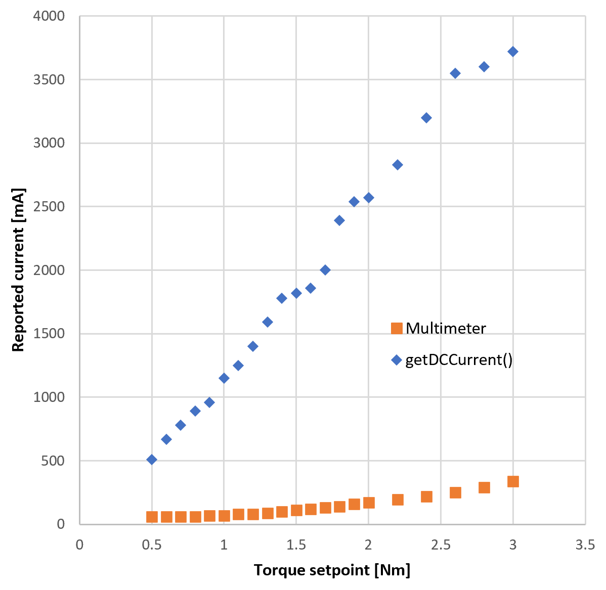
Which seems like it would just be off by a factor, but looking at the ratio between the measures, it’s not:
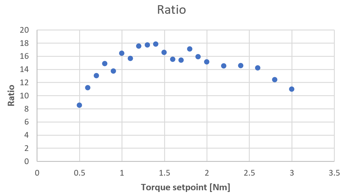
Does anyone have any suggestions of what I could try to debug this?
Thank you very much !!
Motor Current is different than Power Supply or Battery Current.
Thank you! Very interesting! Is there a way to get power supply current?
I think it’s supposed to be something like that:
battery current = (vdid + vqiq) / vbat
Thanks for the suggestion! I’ve had a chance to try that in 2 modes (all in SVPWM voltage control):
Torque FOC
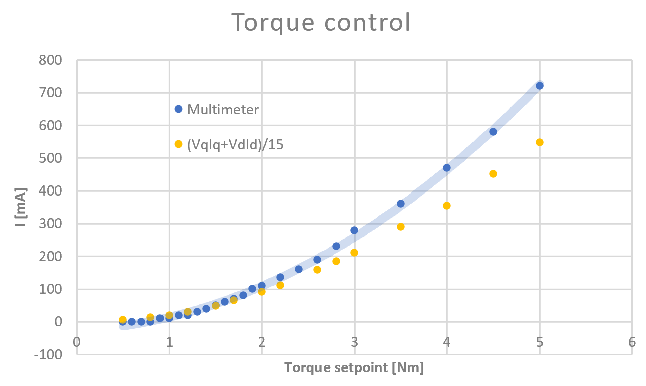
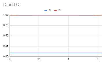
Here, the calculation seems to almost work out, except for some scaling issue. The motor is not allowed to spin and the torque setpoint gradually increased. The term VdId is always 0 in this test.
Velocity FOC
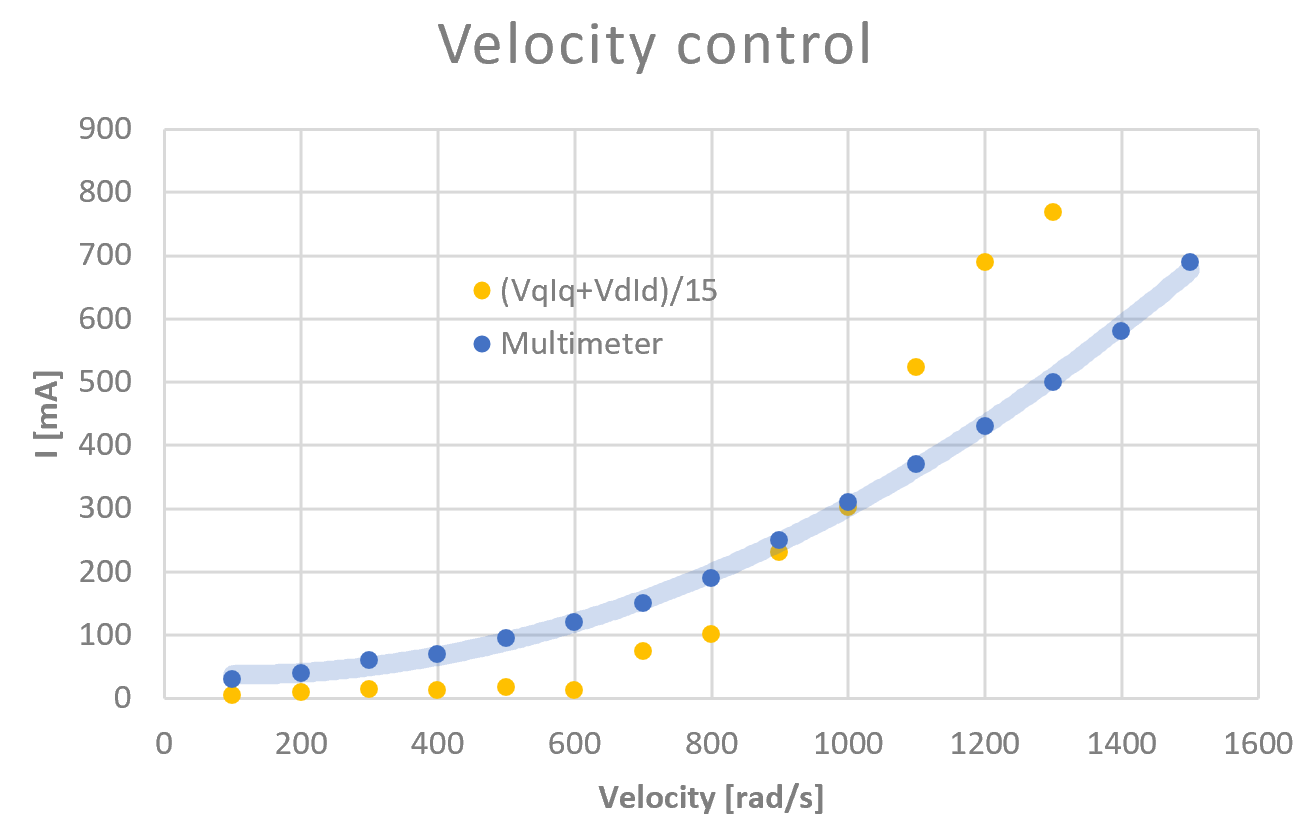
Here, the motor was spinning in no-load conditions. Things are clearly off.
I except that in reality, the motor will be driving a load at speed, therefore I should be getting a combination of both conditions, and the measurement will be off too.
I was thinking more about it yesterday.
The concept behind this formula is the current measured on the motor doesn’t take the PWM duty cycle % into account.
So Vq divided by the power supply voltage * ~0.60 (I missed this factor yesterday) should give you a kind of percentage, that you mutiply by the Iq.
Vd*Iq can be ignored in our case because we aim for 0 Iq.
Also one small discrepancy to take into account is that with your multimeter you are measuring the overall consumption (e.g. buck converter, mcu, … ).
With FOC we measure only the current in the phases.
1 Like
Where does this come from? I would have expected some kind of time-averaged constant to come out to 0.5
The formula I red came from a discord and is 3 (Vd*Id + Vq * Iq) / 2 Vbat.
Which means 0,6666 of your power supply. I couldn’t find any proper formula anywhere else.
Here you can read that maximum Vq is 0.50 for SinePWM (1/2), 0.58 for SVPWM (1/ √3), but you can reach 0.70 if you overmodulate.
But I thought you cannot reach 0.70 because of the deadtime. (came across about this nice document just now)
So I invented 0,60 lol. Could be anything between 0.6 and 0.7 I guess.
2 Likes
They also have a nice animation:
https://microchipdeveloper.com/motor:overmodulation-viewer
![]() Microchip!
Microchip!
@RaphZufferey Would you be able to compare 3(Vd*Id+Vq*Iq)/2Vbus to what you get from current_sense.getDCCurrent(motor.electrical_angle) ?
I have the feeling what getDCCurrent returns is the total motor current, not the DC current.
1 Like
Here are my measurements! I added also Ibus/6 as that seemed to match well in velocity control, but it’s not physically founded. The suggested formula seems to work very well in torque control mode now, but it struggles with no-load velocity control condition.
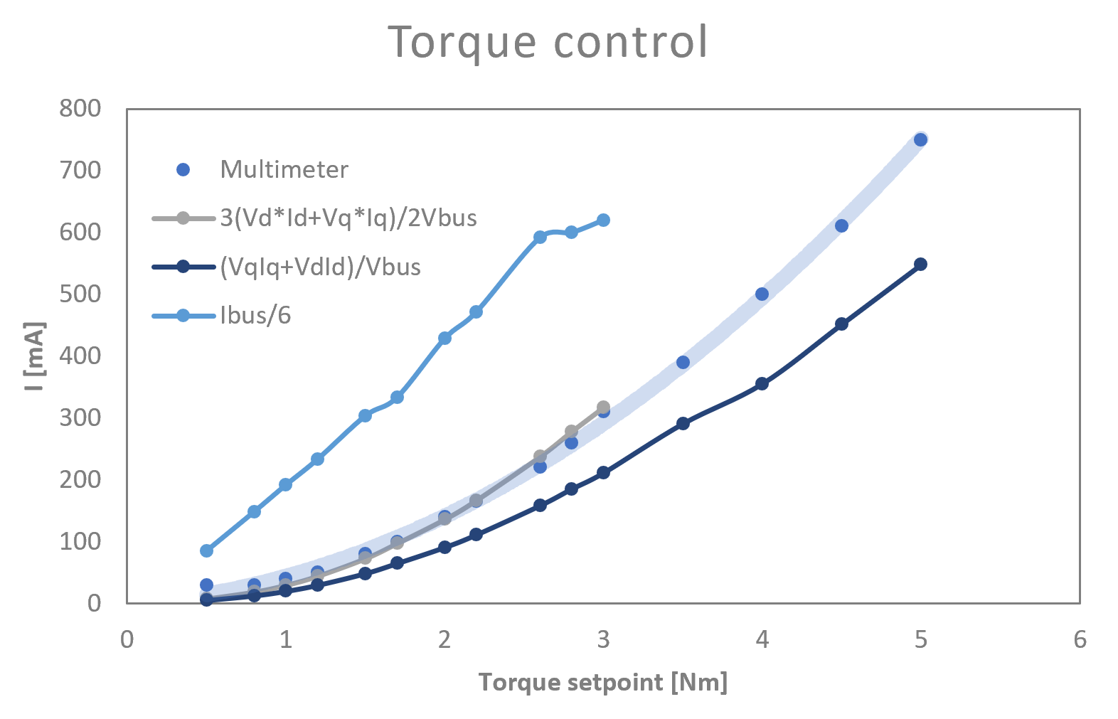
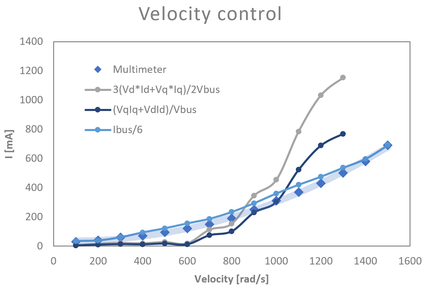
Ibus is current_sense.getDCCurrent(motor.electrical_angle) in those plots
But are you comparing Torque mode with load and Velocity mode without load ?
Exactly! That should get me the 2 extremes of no-load and stall behavior.
BTW, I did substract the current draw from the MCU, so these measures capture current draw from the BLDC only.
So it has nothing to do with the velocity mode. I guess it’s the same with torque mode without load.
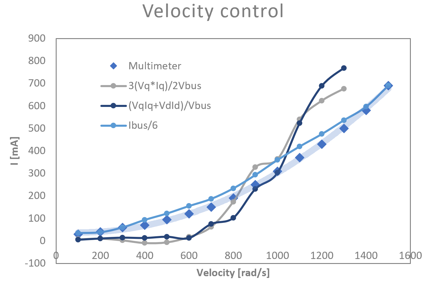
I think with no load it’s more difficult to use the current measurements, there is much more noise. Is it better with only 3(Vq*Iq)/2Vbus ?
Maybe you have a chance to try using the adc calibration as well.
Adding the following here:
// Run adc self-calibration
HAL_ADCEx_Calibration_Start(&hadc1,ADC_SINGLE_ENDED);
HAL_ADCEx_Calibration_Start(&hadc2,ADC_SINGLE_ENDED);
I think I have an idea why Vd*Id makes it worse.
In this post I was showing that a delay between current measurement and angle measurement wrongly increases the measured Id.
As the speed increases, Id is more and more off.
From the other side, Ibus doesn’t seem to be impacted, because it’s only using the angle to define the sign of the current, not to derive Id and Iq.
Maybe you can try this also (3XIbus*SQRT(Vq*Vq+Vd*Vd))/(2*Vbus)