Highly scientific FOC Simulation

Here is the spammer again.
Wanted to share something I used last few days for learning purpose.
It’s clearly not a scientific tool but gives a good intuition about how FOC works.
It’s a very simplified FOC simulation in a gsheet :joy:

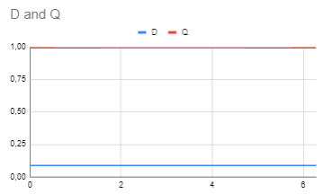
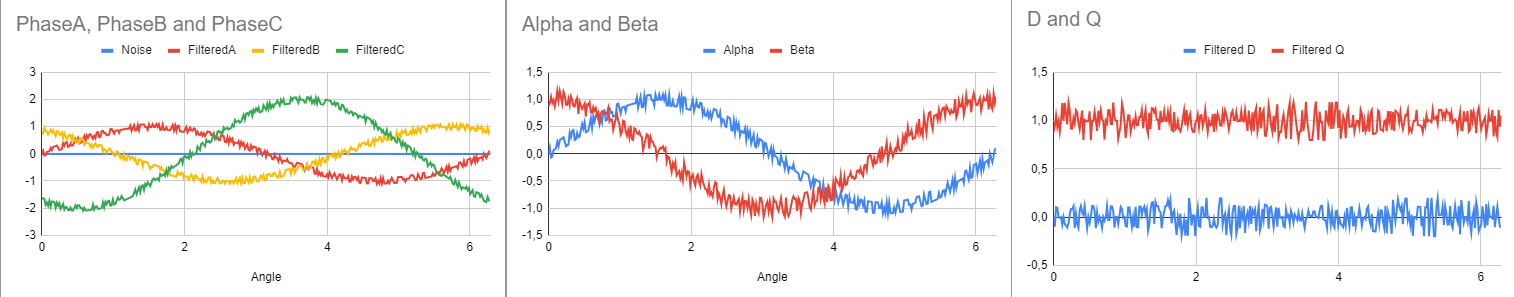
In the Phase current to DG tab:

  • If you enter a different gain for phase A (e.g. 1,1), this makes D/Q currents wobbly, the PIs will have to compensate this. With good hardware I guess it shouldn’t happen.
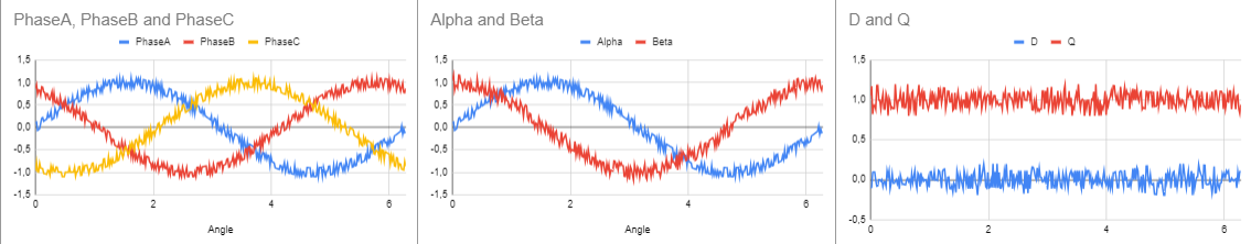
  • If you enter a delay (e.g. 0,1), it introduces a lag between the rotor angle and the sensor angle, this shows not measuring the current and the position at the same time can introduce an error in D and Q (a little) current measurement, reducing the efficiency.

in the DQ current to PWM tab:

  • increasing D current (e.g. 0,5) not only introduces a shift in phases, but also increases the amplitude

And another more advanced motor simulator

You must be thinking, my phase currents don’t look like that. Fair point, let’s add some noise:

Someone proposed to filter the phase current, great idea !!! let’s do it:


It looks much better now. But why did the D current increase ? Oh no we introduced lag !!!

The same would happen if filtering Alpha and Beta… What about filtered the D and Q currrents ?


Ah, much better !!!

But my sensor is slow, it’s not updating often!!!


Oh no !!! D axis current is off and wobbly! More work for the PI controller…

Lukily we can use sensor smoothing !!!

OK I stop bothering you :joy:

Very informative and entertaining.
But we need filtering,unless we have stable signals without glitches.
IMHO these glitches are the bigger problem.

Yes I am showing filtering D Q currents works better, that’s what SimpleFOC is doing. But it’s not perfect either…

Changing phase C current doesn’t impact Alpha/Beta and D/Q currents, how come ? :thinking:

Because Ia+Ib+Ic= 0 (Kirchhoff’s law), only 2 phase currents are enough for FOC.
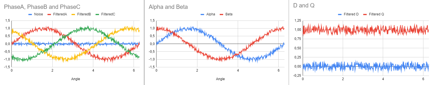
But why do we even measure 3 currents then ?

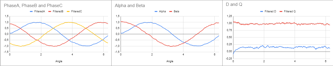
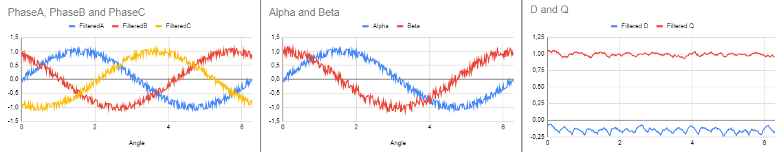
In reality, the total of phase currents don’t add up to 0 because of inaccuracies in hardware, and noise during sampling. One of the reasons why it’s useful to have 3 phase currents is that this can be used to slightly reduce the noise by sharing this error between the 3 phase currents:

Added different modulation types and the effect of deatime on line to line voltage in the DQ to PWM tab if you are interested: