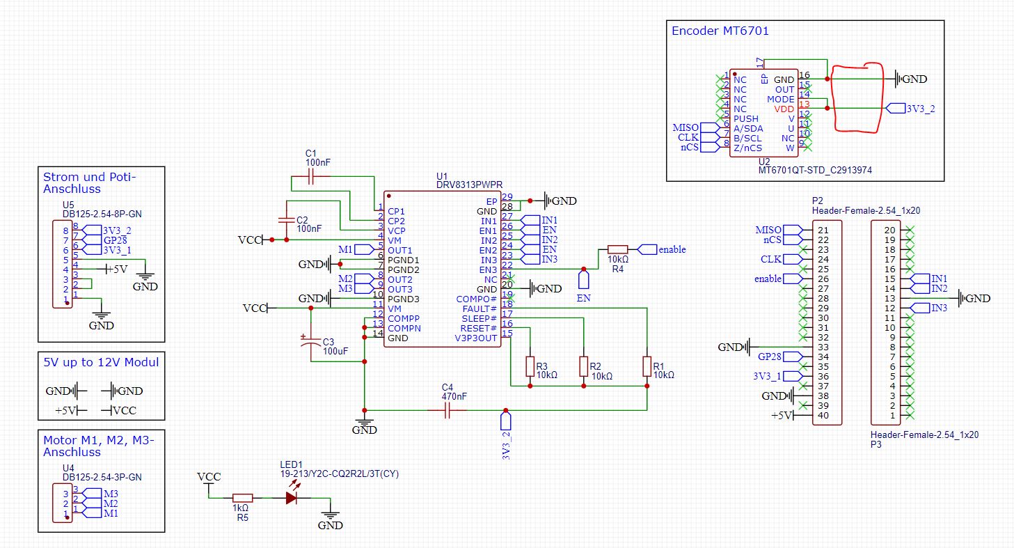
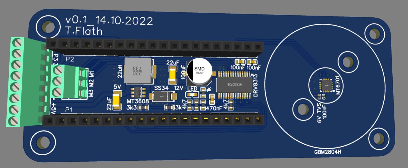
I used the QFN model. But I think they are the same functionality unless you want the pins for UVW output.
For the MT6701, so far I have only got the SSI mode to work.
ABZ mode is an incremental encoder mode, like an optical encoder with ABZ outputs. It can be used with SimpleFOC’s Encoder class.
So far I have not got the ABZ mode to work, maybe its a mistake in my circuit, or maybe I just haven’t tested enough - I only gave it one short try so far.
The SSI mode works well, but only if this chip is the only device on the SPI bus. You can’t attach other SPI devices to the same bus.
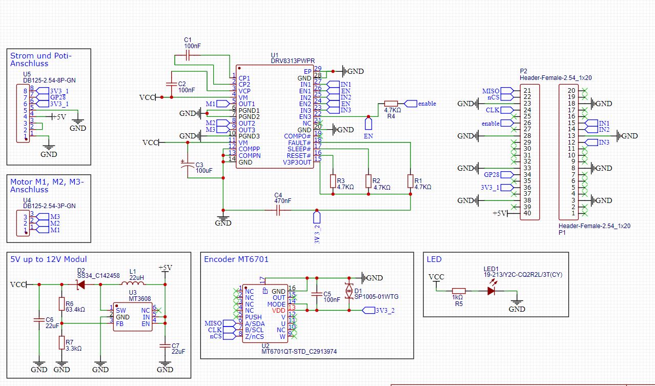
That’s the circuit I made. The switch (in theory) changes between the SSI/I2C and ABZ modes.
When nCS is low, it should answer in SSI mode. When nCS is high, it should work in I2C mode.
What’s the headers for? A BlackPill MCU?
→ ABZ, SSI and I2C modes would all want different pins:
ABZ mode can use any pins supporting interrupts, but if you can attach the ABZ outputs also to the pins of the same timer on STM32, you can use the hardware encoder feature.
SSI mode wants a connection to a SPI bus
I2C mode needs pins on an I2C bus
Note you can attach the signals to multiple pins, just put the pins for a protocol you’re not using in input mode.
Hi Richard,
I use the raspberry pico and I want to use also the SSI like you, so I’m sure that will work
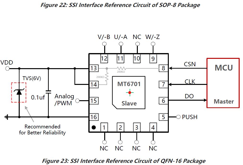
I found a picture in the Datasheet of the M6701 for SSI Mode:
These are good questions, and I do recommend to find out how to verify the design in EasyEDA - but I’m afraid I can’t help much there, as I’m not an easyEDA user - I use KiCad…
In KiCad it begins with the schematic, and continues with the design rules of the layout. I assume easyEDA has similar tools. The process involves setting the design rules to match your Fab’s capabilities, and then applying them to the design, fixing any errors the checker finds. Since easyEDA and JLC are associated, I would expect that to be pre-configured and very easy to do, but I don’t know.
In terms of simulating the design, I’ve never done this for a motor controller, setting up a simulation for such a complex design greatly exceeds my skills with such tools. I also suspect you would be missing spice models for many components.
So once my design checks out according to schematic and design rules, I Fab it and then test the function on the resulting prototype boards.
In terms of components, you can just generate a BOM from easyEDA and upload it to JLC - maybe it’s even possible directly from wi5in easyEDA. JLC will then identify the components and quote you prices according to the BOM. At that point they will flag anything they can’t source or that costs extra.
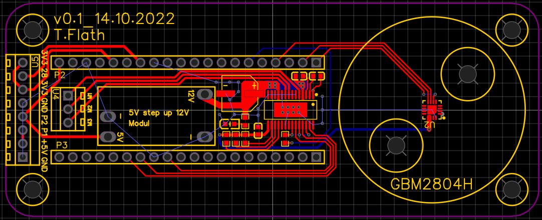
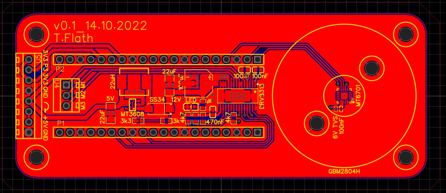
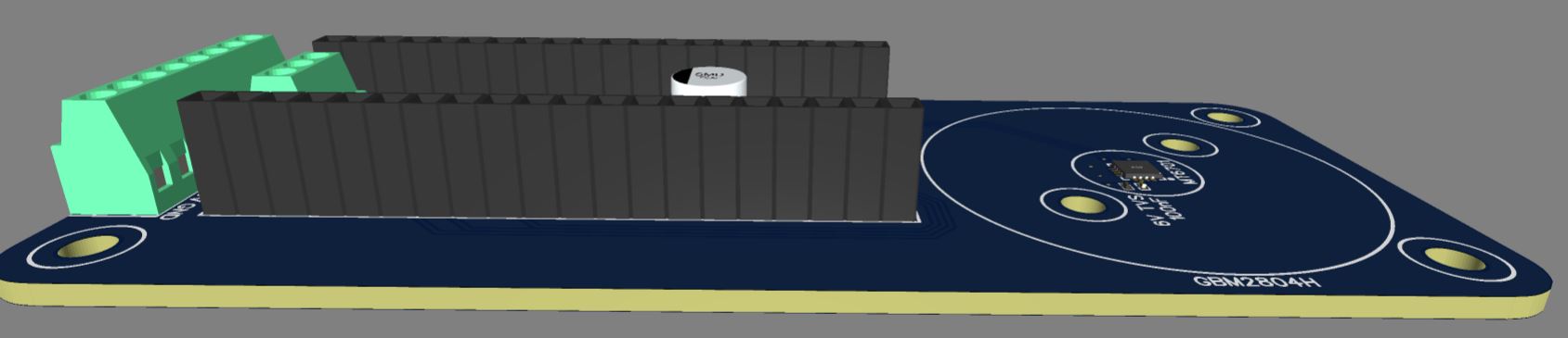
Another good thing to do is to check the 3D view of the design - in your case you are mounting a MCU above an electrolytic capacitor? You want to be sure that the parts will physically fit and the MCU’s bottom doesn’t touch the cap. Or is the MCU on the other side?
Closest you could get from the basic components is
P6SMB6.8CA/TR13 C78395
But that’s not a 603, it’s a DO-214AA, compared to a 603 that’s Godzilla vs. Ant Man.
The closest extended in good stock I could see in a 603 package is this:
D5V0L1B2LP3-7 C282418
However the stand-off voltage is 5V and clamping is 14.
If you are trying to protect 5V, then C282418 will work. If you are trying to protect 6V then we need to dig deeper.
Cheers,
Valentine
PS I suggest you don’t just replace in the BOM but go back and replace these components in the schematics and make sure you reroute and rebuild your copper pours and check the DRC because the footprints are always slightly different and will create a problem, unless you REALLY know what you are doing.
Plus, next time you fab you have to dance again so might as well fix your schematics with those in stock more generic components.
You could also try getting quotes from other Fabs, like PCBWay. I think you’d get a $30 assembly with free shipping deal for this design, so then its $30 + components, for up to 20 pieces. They also have a “first order free” deal for new customers, not sure if it would work for this design or not.
PCBWay has no surcharges for extended components, so if JLC is charging a lot for these it could be cheaper to look elsewhere.
Hi Valentine,
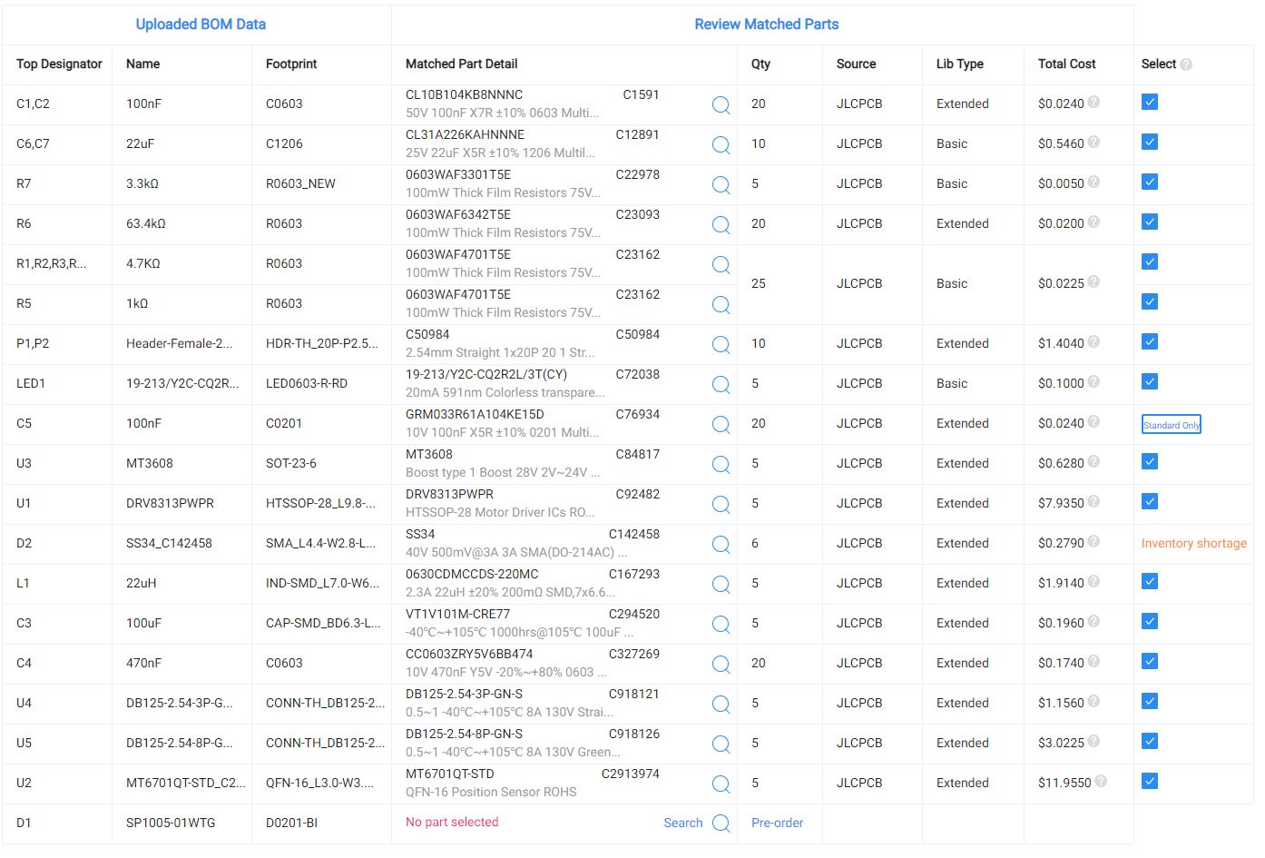
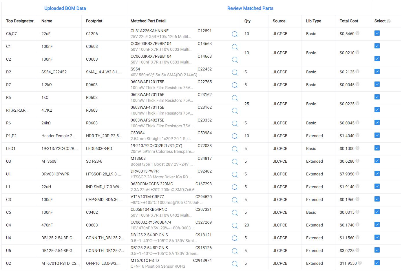
I have now knocked out the D1 (it was still extended), which is only recommented according to the data sheet.
Here is the parts list, can something else be changed from extended to basic?
The P1,P2,U1,U2, U3, U4 and U5 should stay that way or is there maybe also a posibility to change it to basic?
There are no basic connectors, all are extended. You have the option of leaving them out of the BOM and soldering yourself manually, however, since you want it to be out of the box, you have to pay extra for the components and soldering.
As @runger mentioned you may explore other fab facilities, however, JLC at that point is probably your best choice if you have not done this before due to them being fully end to end integrated.
ok, then it seems to fit for now. There are a variety of settings for the board. Is there a guide or a recommendation for the creation of the boards? Is the thickness of 1.6mm ok for this size?
I created some time ago a guide to order one of my Mosquito boards step by step, it’s even using the same driver as yours, please see how I did it here:
Does the mt6701 sensor need pull-up resistors? or is it the same as with your encoder. There weren’t any in there. If I need pullup resistors, could I do that with the software? The 5 boards for 75 euro have been produced at jlcpcb and are now being shipped