The Datasheet does not actually say… I assume that yes, the ABZ lines need pull-ups, but it doesn’t explicitly say.
I2C needs pull-ups, as normally, while SSI does not need pull-ups according to the datasheet.
For this reason I didn’t put the pull-ups on my board, since sometimes they’re needed and sometimes not…
You can try with the MCUs internal pull-ups, it might work, but it might also not work since the MCU pull-ups are usually quite weak…
Hi Richard,
I have very good news. The board arrived this Thursday and I got it working with the MT6701 sensor. It works great on the USB on the PC. However, and here’s the bad news, when I plug it into a power bank, it shuts off after about 30sec. It appears to be an automatic shutdown. Apparently the current consumed is so low that the power bank switches off. Are there settings in the software so that I can get the minimum current higher?
#include <SimpleFOC.h>
#include <encoders/MT6701/MagneticSensorMT6701SSI.h>

// motor data
const int pole_pairs = 7;
const int pwmA = 4;
const int pwmB = 5;
const int pwmC = 6;
const int enable = 20;

// sensor data
const int clk = 18;
const int miso = 16;
const int nCS = 17;

// potentiometer
const int poti = 28;
const int z = 2.5; // zero speed
float i = 300; // gear
float velocity_ = 0;  // motor
float target_velocity = 0; // poti
unsigned long startTime = millis();

// motor instance
BLDCMotor motor = BLDCMotor(pole_pairs);
// driver instance
BLDCDriver3PWM driver = BLDCDriver3PWM(pwmA, pwmB, pwmC, enable);
// magnetic sensor instance
MagneticSensorMT6701SSI MT6701(nCS);

void setup() {
  pinMode(poti,INPUT);

  Wire.setClock(400000);
  MT6701.init();
  motor.linkSensor(&MT6701);

  driver.pwm_frequency = 100000;
  driver.voltage_power_supply = 12.6;
  driver.voltage_limit = 12.0f;
  driver.init();
  motor.linkDriver(&driver);

  motor.controller = MotionControlType::velocity;
  motor.voltage_limit = 12.0f;
  motor.PID_velocity.P = 0.7;
  motor.PID_velocity.I = 0;
  motor.PID_velocity.D = 0;
  motor.PID_velocity.output_ramp = 1000;
  motor.LPF_velocity.Tf = 0.0175;

  motor.init();
  motor.initFOC(2.55, Direction::CCW);
  _delay(100);
}

void loop() {

  float target_velocity = analogRead(poti)/i+z;
    if((millis() - startTime) > 75) {
      if (target_velocity != velocity_)
      {
        if (target_velocity > velocity_)
        {
          velocity_ = velocity_ + 0.2;
        }
        if (target_velocity < velocity_)
        {
          velocity_ = velocity_ - 0.2;
        }
      }
        startTime = millis();
    }

  motor.loopFOC();
  motor.move(velocity_);
}
Honestly, as Valentine said, I think you’re the first person to ask for a way to make the system use more current (when it’s not needed)…
Offhand, I can’t think of a way to do it without incurring other disadvantages like, overheating the motor for example.
You could look at raising the I term in the velocity PID somewhat… but I’m not sure it would make enough difference. And after all, you also don’t want the power to cut out if you set the speed to 0 for more than 30s…
I think Valentine’s suggestion of a resistance isn’t such a bad one, but another idea could perhaps be some LEDs? A few NeoPixels turned up nice and bright can consume quite a bit of energy, while making your project more beautiful… I love LEDs you can get NeoPixel matrix or ring PCBs quite cheaply.
Or else a different battery, but of course the power banks have several advantages over more primitive RC style power packs… so I do understand why you’re using it.
Hi together,
you are right. I shouldn’t increase the power consumption additionally and should be happy that the controller consumes so little power. I found the following on the web:
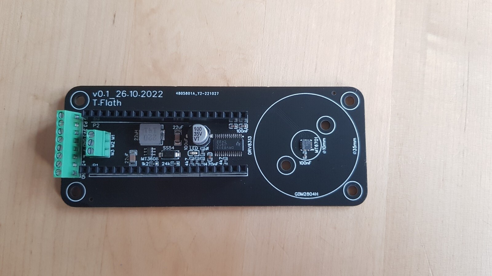
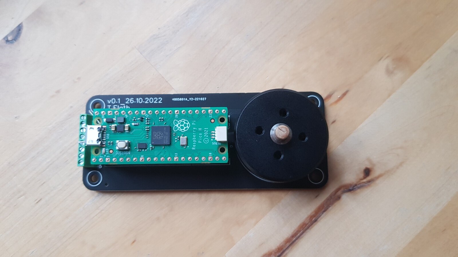
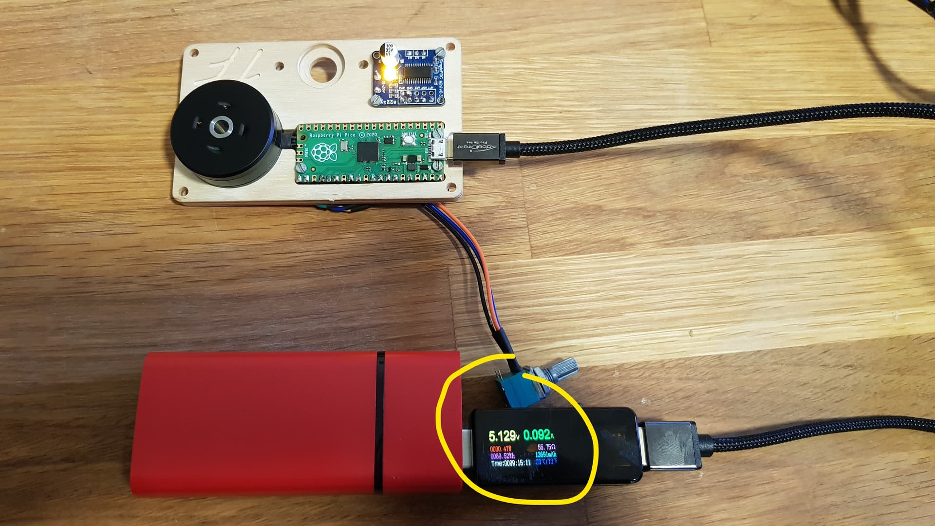
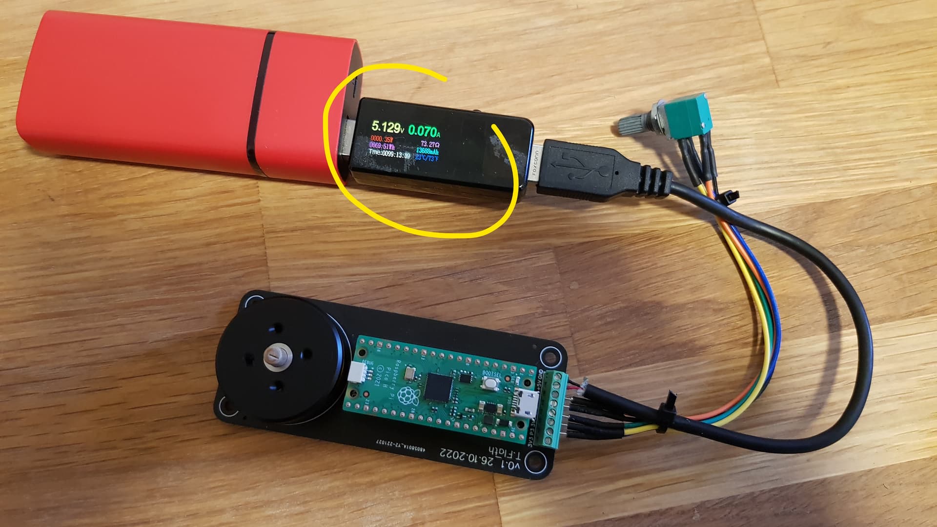
Here you can “wake up” the power bank with just a few components and I will check that I integrate this into my board. A friend of mine has a USB current tester that you can plug between the board and the power bank. Let’s see how much current is drawn now.
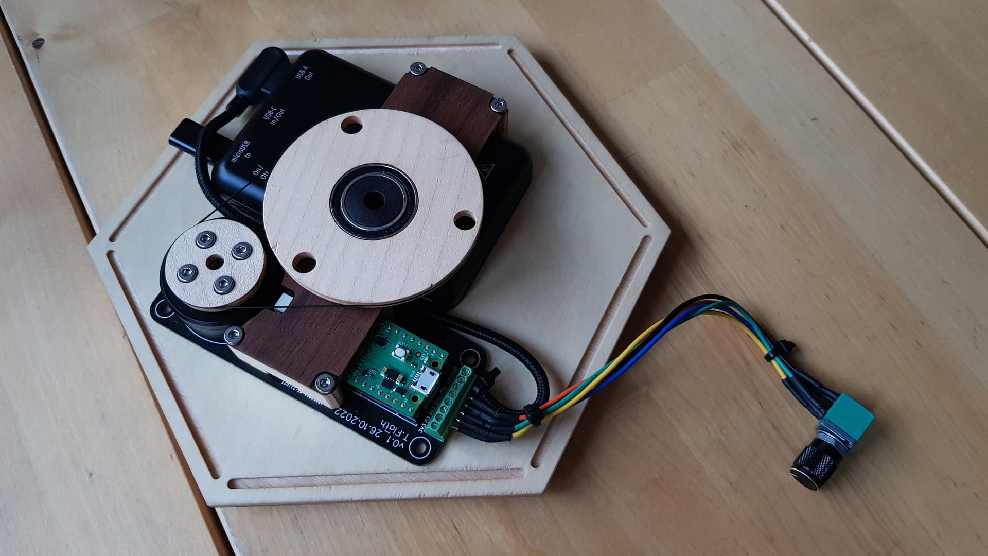
Here are also some pictures, the board is 100mm x 40mm:
Hi Valentine,
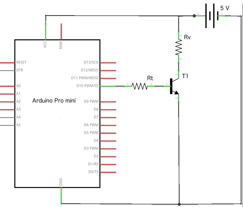
I found another homepage for the problem. A “BC547C” transistor (T1) is used here. Can you please look at jlcpcb for a comparable smt transistor that is also basic? I would like to integrate this circuit here into my board.
Could you please next time put a @ in front of my name, I will get a notification automatically and respond much faster? I just saw this post. Like this:
I will check, give me an hour. I will respond in this post as an edit.
Cheers,
Valentine
Edit:
There is a more powerful transistor which is a basic part# C9634
However the breakdown voltage is 30V. If you stay under 30V you will be OK with that one.
The closest I could find as a basic part replacement is part# C2149
This transistor however dissipates only 200mW and the one you show me dissipates 650mW.
If you only need this to keep the power pack on, by dissipating a small amount of current, and you are under 30V, you will probably be OK with the second one. The first one is too small I think.
There are no other BJT/NPN transistors as basic parts from JLC with that characteristics.
Hello together,
I once measured the current consumption, it is about 90mA for the soldered together “wood” variant and about 70mA for the compact variant. The battery seems to shutdown at about 80 - 85mA. Some powerbanks require about 90-100mA to stay awake. I chose to burn about 33mA with a 150 ohm resistor through a transistor. That’s about 103mA for a short time.
The choice of the transistor was difficult for me. I have now ordered the MMBT2222A (C8512), because it is available at JLCPCB (as basic part) and also at a store near here. As soon as the things are there, I will try it.
The powerbank you got by the looks of it is about 3000mAh so if you burn 100mA to keep awake you will drain down to zero it with no motor load in 30 hours, or a little over a day. Is this acceptable for your use case?
Hi valentine,
the powerbank has 5000mAh. Due to the discharge protection, you will never be able to completely empty the power bank. What could also be included is that the power bank is no longer the newest. With the 90mA variable, I reached a duration of approx. 35 hours before the power bank was “empty”. At about 70mA you should get about 45 hours (mayby more?) and that’s really a value that I like. A friend of mine said that you could get even more out of it by putting the pico into sleep mode for a short time and then waking it up again after a few quartz clocks. But that’s not on my agenda yet
Hi all,
yesterday I plugged a larger powerbank with 10,000mAh to the assembly. After a few minutes the motor became very very warm and stopped. After it cooled down, I turned the motor back on with the potentiometer. The motor spun very fast and the current was at about 0.5A and way too high (otherwise about 0.07A). I tried another board yesterday evening to exclude that this one is broken. same result. after I took out the defaults again at motor.initFOC() it works again. I suspect that something is deformed by the strong heating or something like that and the “offset” of “2.55” at motor.initFOC () is wrong now. I wanted to change this parameter with
and the Monitor tool. However, then always comes the message that the port to which I have plugged the pico is occupied. Do I have to do anything else with the Pico?
Ouch! Be careful, if the motor overheats it can be permanently damaged - the insulation can melt off the phase wires, and the permanent magnets can demagnetize… most magnets don’t like temperatures above 85°C, but it depends on the type and quality.
Yes - a frequent problem is with 3D-printed parts, which can deform or become soft already at quite low temperatures. I think your analysis is correct that something moved somehow. You’re using the MT6701? Often it is the sensor magnet or its attachment which moves…
Typically this means the COM port is already being used, for example by a serial monitor. Are you sure the serial monitor is not running?
Which tool are you using to see the values on the PC side?
Hi Richard,
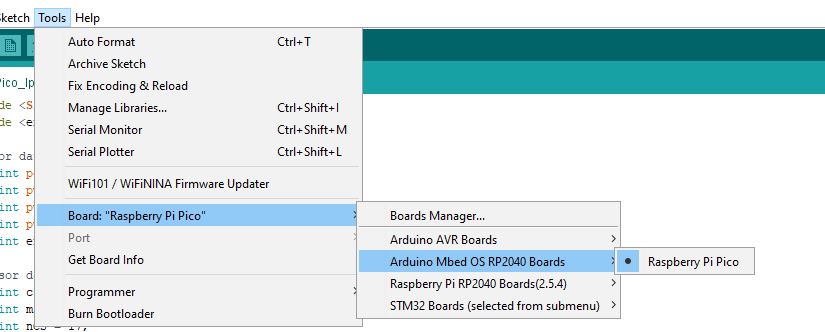
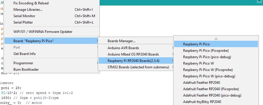
I’m using the MT6701 right and I’m using the Arduino IDE Software.
What surprises me is that about 2 months ago there were no problems or I do something else. Do I have to press the button on the pico when I connect it to the PC?
In the Arduino IDE program this error is displayed as text. I could copy it here when I get a chance.
I’m still trying to figure out the cause why the motor got so very hot. The 5200mAh powerbank had max output of 1.0A and the larger 10000mAh powerbank has max 3.1A output. Could it be that this powerbank simply delivers more current than the smaller powerbank? I put a current meter in between yesterday, but everything was fine. Or if the offset is not 100% correctly set, the motor draws more current…
If the magnet slips out of alignment, then the electrical angle input to the algorithm will be wrong. This angle is used to determine the “direction” the force should be applied by the stator’s windings, to pull the rotor forwards… If the magnet position becomes completely out of phase to the rotor position, then the FOC algorithm will put all the energy into the D axis instead of the Q, which means the motor’s magnets are pulling with maximum power in a direction which results in no motion. This will effectively mean the motor is being used as a heater rather than a motor…
The amount of heating in the winding will depend on the cross-sectional thickness of the windings, and the amount of current passing through them.
1A can be quite enough to produce a burning hot motor after 10 minutes… it depends on the winding resistance.
Possible, but normally when you go over the max current the power bank either burns/explodes, or (hopefully) its protections kick in and either lower the voltage or cut off power altogether.
Hi together,
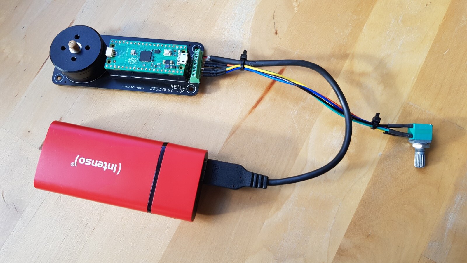
here is a picture of the half-finished turntable. I have one more question regarding the turn-on time. When I flip the switch, the motor takes about 2 seconds to start turning. Can this be reduced to one second or less?