hi runger,
i’ve been thinking back and forth for a while about how i’m going to continue. considering that the b-g431b-esc1 has become quite expensive and i would like to build several such turntables and that it seems to consume quite a lot of power, i decided to use a different mcu. I have dealt with the bluepill and this seems to have problems with the assembly, connection and i can only buy it via aliexpress. an alternative to this is the rassperry pi pico. It is verry cheap, fast and i can buy it at reichelt.de. and i know, it has not the problems. plus the simplefoc mini, which will be available here soon. do you know when the mini will be available? because this combination is very, very cheap, I can afford such an as5047p. however, I saw that simplefoc only supports pwm for the pico. are you working on making the pico also support spi or i2c?
Hey Thomas,
That’s old information, I think. I rushed to support the RP2040 MCU (used on the Pico) right when it came out, and Arduino framework didn’t have good SPI support for it yet.
But that was fixed, and SimpleFOC has since been updated to enable the SPI and I2C support for RP2040…
I can’t give you an answer on the mini, I’m afraid… Antun is working on that.
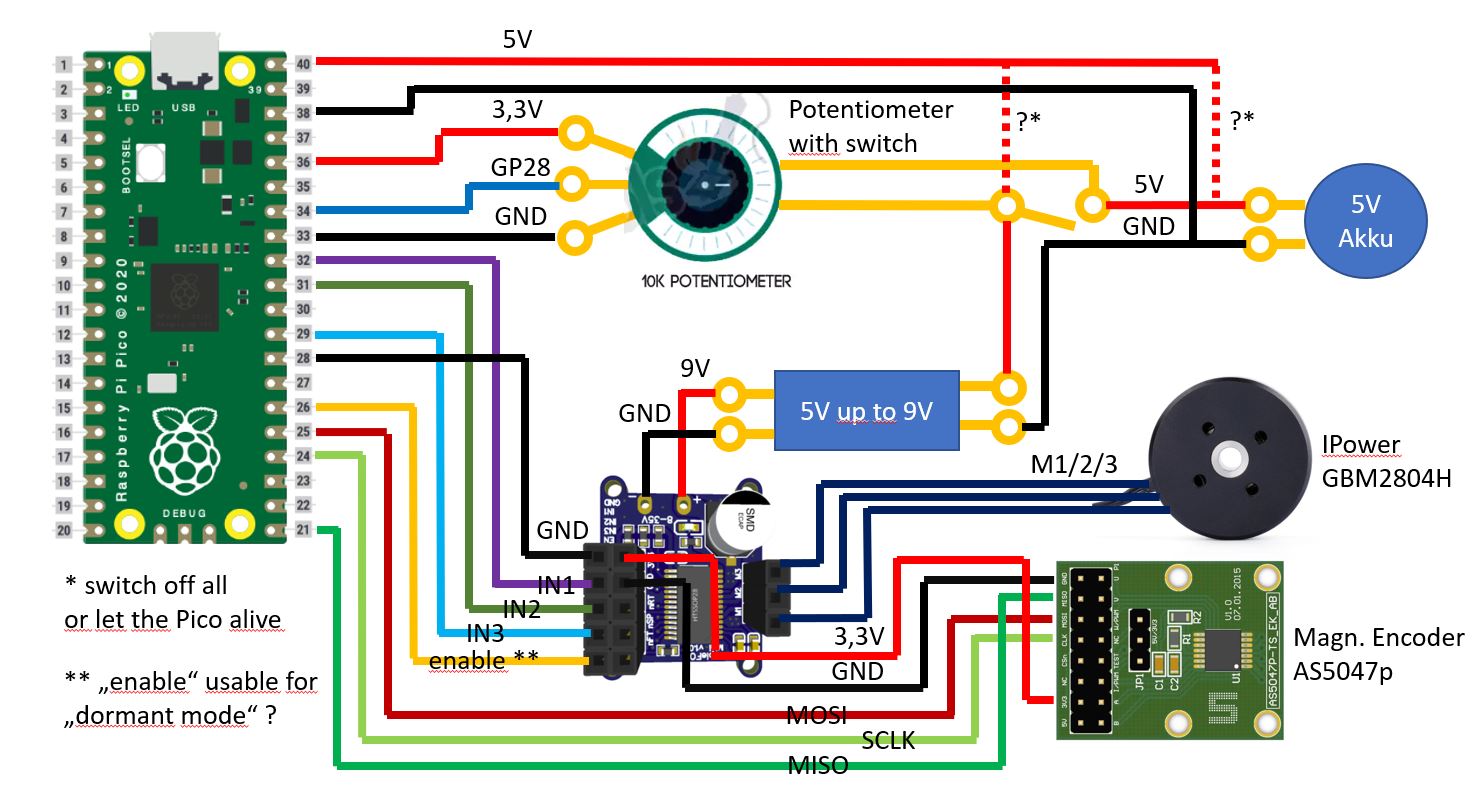
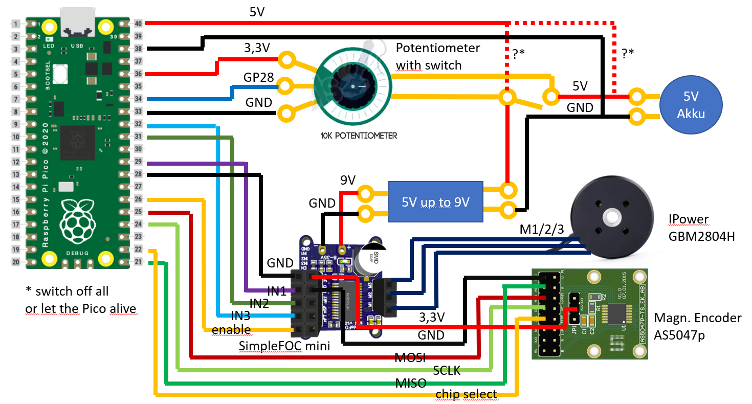
In preparation I have created a sketch with the components. I have a rotating potentiometer with switch in the middle. The question is, is the example wired correctly here? Or can something else be simplified here?
I have in mind that the program first initiates the sensor and the motor when it is switched on, and that takes about 2 seconds. If I continue to supply the pico with power when it is switched off, the initiation should no longer take place when it is switched on. It would be nice if I could reduce the power consumption of the pico in this state, so that the battery is not unnecessarily drained when it is switched off. I have read that there is a “dormant mode”.
Hey Thomas,
- I trust you checked the Pico’s pins - I won’t recheck.
- The potentiometer has an analog output, it might be good to smooth it a bit, and it should be connected to an analog pin on the pico.
- Yes, you can use the driver enable pin to disable the driver output, reducing power consumption
- power management is a major concern. Your circuit will work, but why not use a 9V battery, and a 5V buck converter to produce the 5V? This will be a better setup, as the motor is the part that could draw most current, and should get it directly from the battery, with no conversion losses. The 5V rail only has to power Pico, driver and sensor - it will only be a few mA. So you can use a cheap, small, low power buck converter to produce the 5V. Much less heat will be generated == much less waste
- Also, can you get a 5V battery? Batteries are typically multiples of 1.5V, 1.2V, 3.7V, 4.2V - depending on type and chemistry. 5V, AFAIK, is not a common voltage for a battery. Of course there are “USB Power Banks” which do 5V, but these are typically lithium batteries, and contain internal voltage conversion.
- But you can get a 9V battery…

- I am sure the Pico has a sleep mode… you’ll probably need a way to wake it back up though. Maybe a push-button switch?
- The SimpleFOC mini has an on-board 3.3V LDO - you have the sensor connected to this, but you could also power the Pico with 1.8 – 5.5V via its VSYS pin -
so 3.3V from the LDO can power it too, and you can get rid of the buck converter alltogether?
Edit: the LDO only provides 10mA - that won’t be enough
Hi runger,
thanks for your anwer ![]()
background for the 5V is the following. The powerbanks are available with high mA numbers very cheap and are rechargeable and everyone has a charger for the phone. For a 9V battery you need an extra charger or you have to change the battery every time.
For the dormant or sleep mode I thought, you can take the enable as a signal, if enable is on, so the driver has power, it wakes up the pico, if the driver has no power, it brings the pico into the dormant or sleep mode. Or is that not possible? But first wait, I ordered the parts for it, I already have the pico. Motor and encoder should come next week or so, the driver sends me @Antun_Skuric for testing (thanks again at this point)
Hey - the EN signal is an input to the driver, and output from the pico.
You have to set it from the pico, so you can’t use it to control the pico’s sleep. You need a second input to the pico itself.
I understand your choice to use a powerbank, it makes a lot of sense from the convenience point of view. The power-bank will have a maximum current output rating, so you have to make sure you do not draw too much power from it.
For the small motor you are planning to use it will probably not be an issue, but for larger motors the problem is that the power-banks can’t deliver enough current.
ok,
I have seen in some pictures, that this enable wire is optional. Can I remove it?
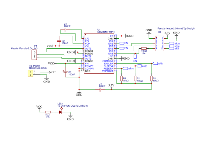
In 8313 everything is mandatory, there is nothing optional. If you do not, it will go dark. Check out the Mosquito design thread schematics, I’m using 8313, it’s working. Also, another OP there attached his schematics on the same driver, so you have quite a lot of existing work to rely on.
Hi together,
short update:
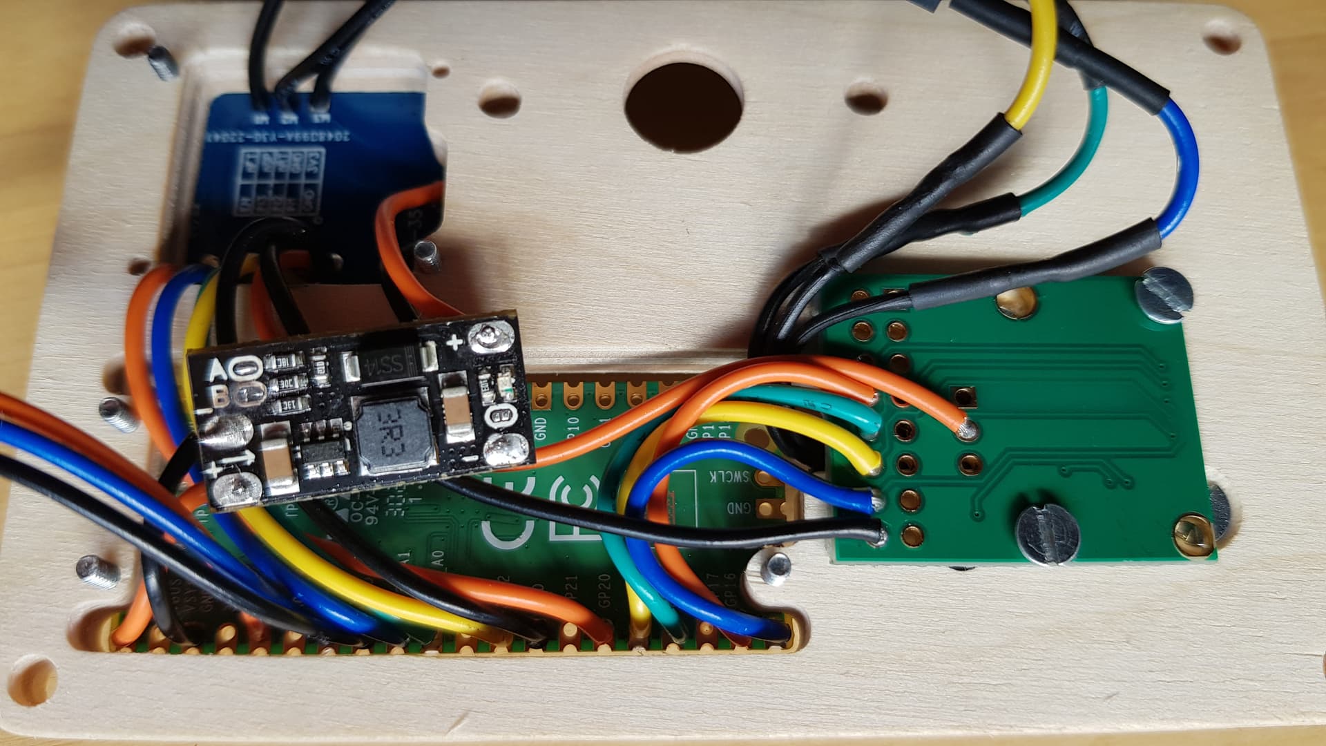
I now have all the parts there and have assembled and soldered them over the weekend according to the picture above here except for the switch for the external battery. Here I use the USB interface for now. Yesterday I installed the drivers for the Pico at the Arduino IDE and already got the LED to blink. Next I wanted to get the open loop mode to work.
Is the code given here correct for this?
Unfortunately I don’t know whether to specify the pins 1-40 or the number of the GPXX there. I have tried both and the motor has not turned yet.
// Open loop motor control example
#include <SimpleFOC.h>


// BLDC motor & driver instance
// BLDCMotor motor = BLDCMotor(pole pair number);
BLDCMotor motor = BLDCMotor(7);
// BLDCDriver3PWM driver = BLDCDriver3PWM(pwmA, pwmB, pwmC, Enable(optional));
BLDCDriver3PWM driver = BLDCDriver3PWM(22, 26, 27, 20); // (GP22, GP26, GP27, GP20) / (29, 31, 32, 26)

void setup() {

  // driver config
  // power supply voltage [V]
  driver.voltage_power_supply = 9;
  // limit the maximal dc voltage the driver can set
  // as a protection measure for the low-resistance motors
  // this value is fixed on startup
  driver.voltage_limit = 9;
  driver.init();
  // link the motor and the driver
  motor.linkDriver(&driver);

  // limiting motor movements
  // limit the voltage to be set to the motor
  // start very low for high resistance motors
  // currnet = resistance*voltage, so try to be well under 1Amp
  motor.voltage_limit = 9;   // [V]

  // open loop control config
  motor.controller = MotionControlType::velocity_openloop;

  // init motor hardware
  motor.init();


//  Serial.begin(115200);
//  Serial.println("Motor ready!");

  _delay(1000);
}

void loop() {

  // open loop velocity movement
  // using motor.voltage_limit and motor.velocity_limit
  motor.move(2);

}
Is it right up to this point here for now and should the engine have been rotating?
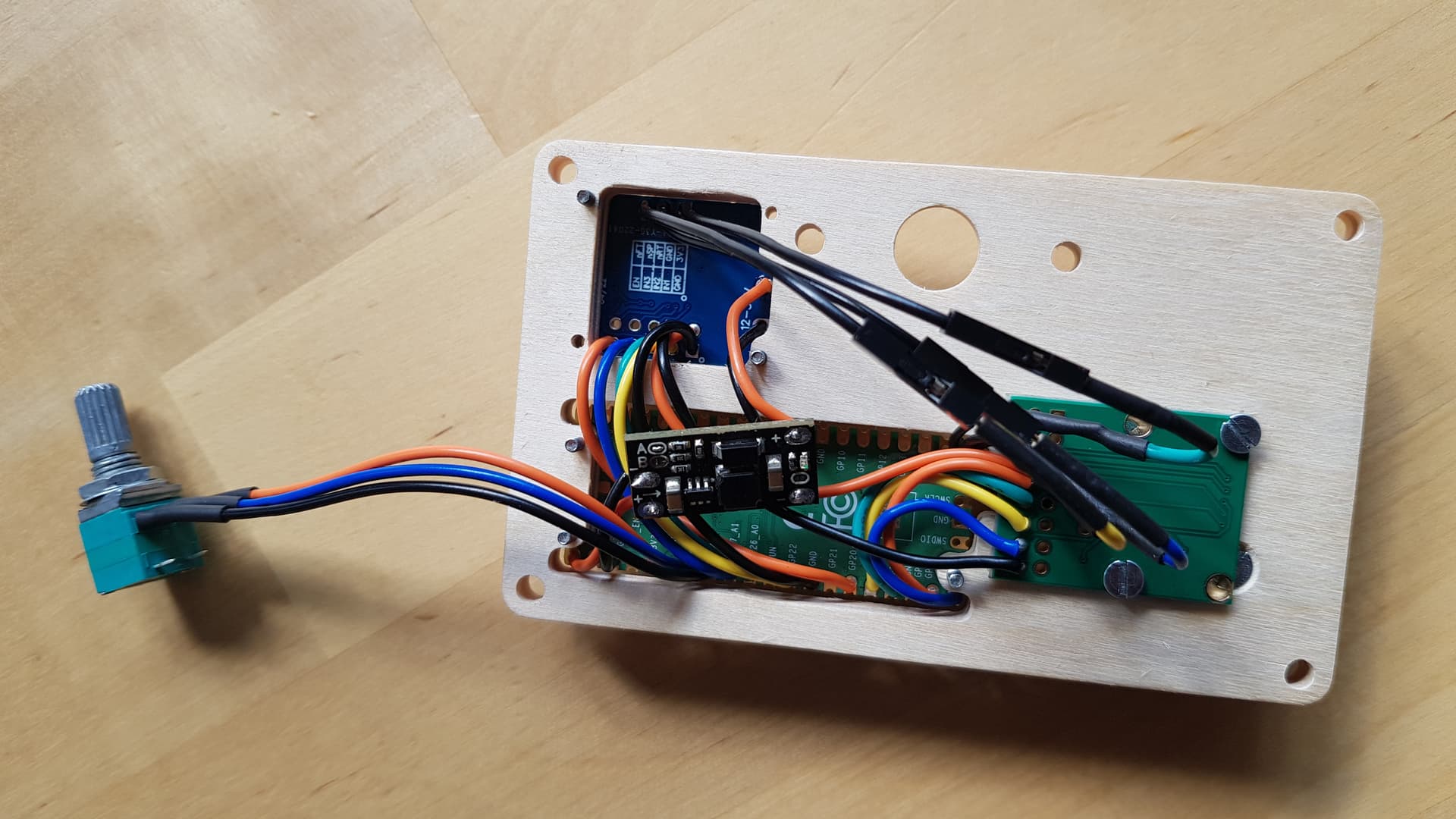
Here are a few more pictures of the setup:
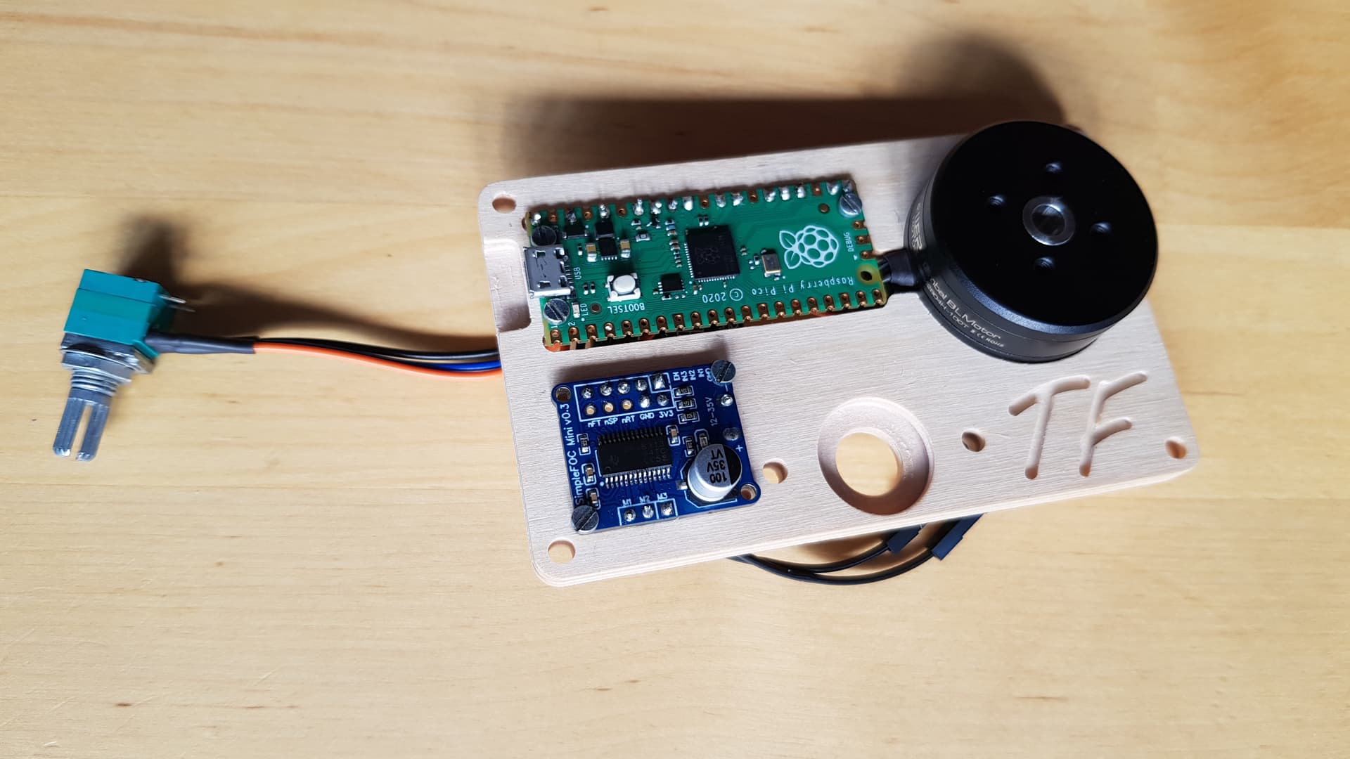
I like this “enclosure” you have made!
I believe using the GPIO #s is correct. So pin GPIO04 is 4.
Your code looks ok at first glance… perhaps you want to add a slight delay to the main loop, like delayMicroseconds(100); to make sure it doesn’t go too fast.
You could also try hooking up the Serial (via USB) and checking the debug output:
  Serial.begin(115200); // enable serial, default on Pico is via USB
  SimpleFOCDebug::enable(); // enable debug output in SimpleFOC
  delay(1000); // wait 1s

  SimpleFOCDebug::println("Initializing..."); // you can also print some messages of your own
the simpleFOC mini needs 12V ![]() only 9V is too less.
only 9V is too less.
Hi Richard,
after initial settings, the motor runs with a battery with 5000mAh about 25h. This is a good value with which I can work. The potentiometer for rotation control I have not yet programmed, but that will be the next step when I get to it.
I have a question to you ![]() you had once tested a very cheap sensor for the encoder, the MT6701. Did you get it to work?
you had once tested a very cheap sensor for the encoder, the MT6701. Did you get it to work?
Background is this: it took me 2 hours to solder all the cables and that’s too long for me. I was thinking of making my own board where I just put the pico on it, because you can also order it with pins. it would be good if this board then included this cheap sensor, the drivers for the motor, the board for 5V up to 9V and 5 connectors for the potentiometer with switch, 2 connectors for 5V + and - for the battery and 3 connectors for the motor.
Is there someone here in the forum who could build me something like this?
Yes, but so far only in SSI mode, and only when there are no other devices on the same SPI bus… I have not made the other modes work so far, but I gave to do more testing.
It’s a sound idea in principle… I think you’re having similar experiences to me and many others here - a prototype setup with wires is good as proof of concept, but hard to really integrate into a more complete hardware prototype, let alone anything finished. The wires flying around are not only a pain to solder, but also make the construction fragile and error-prone.
So once you’ve settled on a design and done some initial testing, I agree that a integrated motor board can be a good way to go.
Unfortunately the semiconductor shortage has made such efforts way more difficult, both from the point of view of finding “finished” products, and designing your own.
There are a number of finished drivers out there, some also integrate sensors. Moteus and TinyMovr are two such projects, and there are other driver boards which integrate the MCU and driver, and work with an external sensor via SPI or ABZ interfaces.
So you could see if you can find an available driver anywhere that suits your needs. Sensor boards with plug connections are available on AliExpress or Tindie. While finding this stuff isn’t the easiest, and the products aren’t always cheap, its certainly less work and cost than making new ones yourself.
On the other hand, if due to features, shape of the hardware or other reasons you decide that making your own is better, then there are definately people here that can help.
In principle I’d be pleased to help, but I have two other ESC projects of my design to finish off first, and another that I’m helping on the software with, so I really can’t take on another one until I finish something else ![]()
But in the meantime I would be happy to help with advice and pointers as much as I can…
Full stack boards are mostly designed with very narrow/specific use cases in mind. It may be hard to find the right one. Also, integrating an angle sensor as part of the board has always been questionable. The mechanical constructions of motors and use cases are so diverse that hard-wiring / integrating a sensor into a board would work only for a very small subset of cases. Colling and mechanical vibrations will very quickly destroy your board. There were couple people who attempted this and they gave up because the board bolted to the motor either cracked, the components solder joints disconnected, the motor overheats and with the MOSFETs also releasing a massive amount of heat it eventually kills the MCU because cooling becomes a major problem. You are not designing a board anymore, you are designing a complete electrical/mechanical/thermal system. That fit-all-sizes generic integrated Holy Grail board sounds very cool and clever, however, in practice, it is a very expensive enterprise, both to develop and then manufacture. You will end up manufacturing with 2oz to 4oz copper to get high current from such small boards and mosfet footprints, dual-side the SMD components, splitting the power and signal sections, using a thick substrate to deal with mechanical stress, realize the cheap components are not good enough and end up using high end but expensive components, weird holes and cutouts to manage stress and dampen vibrations, bare copper fills and bus-bars for high current, the PCB manufacturer will say, no you cannot do that, we cannot cut the board or plate the holes there, etc, and on top of this you will need to add a pretty complex cooling solution. The end result would be so expensive, you might as well buy an off-the-shelf solution such as the mini-cheetah actuator for $200 and move on.
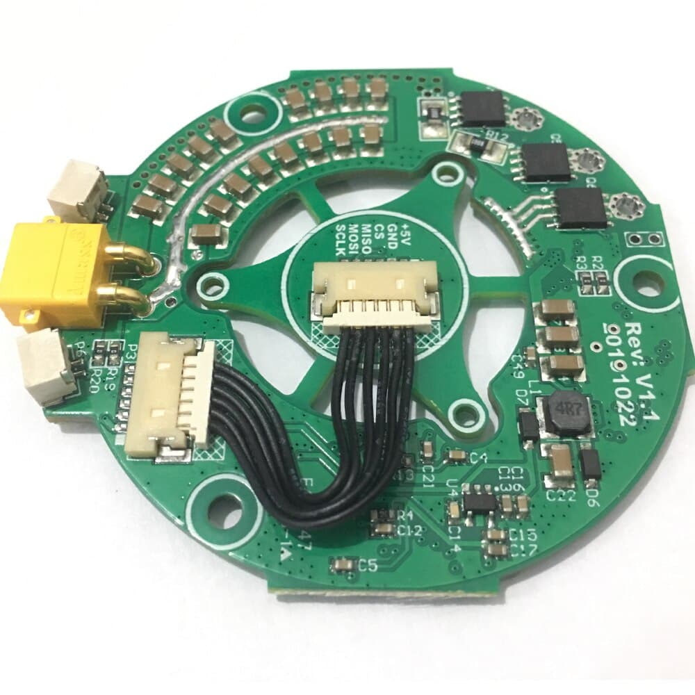
This is the MIT mini-cheetah actuator full-stack board. Not cheap to manufacture.
Anyway, it is possible, but will work only for you, and someone else will come later with a different motor and use case and say, hey, I can’t find a generic enough board that fits my use case and budget.
Absolutely there are plenty of people. But they won’t do it for free ![]() .
.
Cheers,
Valentine
Hi Valentine and Richard,
Thanks for your messages ![]()
That mean it would work similar to SPI but without the MOSI line. That is very interesting for me ![]()
The config works and I just want to put the components on one board so I don’t have to solder so much at least so many cables. And it would be great if I could still integrate the encoder.
I’m not asking for that either, you could also agree on that or not ![]() it all depends on one try
it all depends on one try
I had time yesterday evening and programmed the poti, I could even develop a kind of algorythmus where I have smooth accelerations. So that the engine does not accelerate so much when switching on.
I post the code. Do you see the possibility to save power somewhere else? Or maybe you know what can be improved there. So far the battery runs 34 hours but the more the better.
![]()
#include <SimpleFOC.h>

// motor data
const int pole_pairs = 7;
const int pwmA = 22;
const int pwmB = 26;
const int pwmC = 27;
const int enable = 20;

// sensor data
const int clk = 18;
const int mosi = 19;
const int miso = 16;
const int chip_select = 17;

// potentiometer
const int poti = 28;
const int z = 3; // zero speed
float i = 300; // gear
float velocity_ = 0;  // motor
float target_velocity = 0; // poti
unsigned long startTime = millis();

// motor instance
BLDCMotor motor = BLDCMotor(pole_pairs);
// driver instance
BLDCDriver3PWM driver = BLDCDriver3PWM(pwmA, pwmB, pwmC, enable);
// magnetic sensor instance
MagneticSensorSPI AS5047P = MagneticSensorSPI(chip_select, 14, 0x3FFF);

void setup() {
  pinMode(poti,INPUT);

  Wire.setClock(400000);
  AS5047P.init();
  motor.linkSensor(&AS5047P);

  driver.pwm_frequency = 100000;
  driver.voltage_power_supply = 12;
  driver.voltage_limit = 5.0f;
  driver.init();
  motor.linkDriver(&driver);

  motor.controller = MotionControlType::velocity;
  motor.voltage_limit = 3.0f;
  motor.PID_velocity.P = 0.5;
  motor.PID_velocity.I = 0;
  motor.PID_velocity.D = 0;
  motor.PID_velocity.output_ramp = 1000;
  motor.LPF_velocity.Tf = 0.025;

  motor.init();
  motor.initFOC(4.91, Direction::CW);
  _delay(100);
}

void loop() {

  float target_velocity = analogRead(poti)/i+z;
    if((millis() - startTime) > 75) {
      if (target_velocity != velocity_)
      {
        if (target_velocity > velocity_)
        {
          velocity_ = velocity_ + 0.2;
        }
        if (target_velocity < velocity_)
        {
          velocity_ = velocity_ - 0.2;
        }
      }
        startTime = millis();
    }

  motor.loopFOC();
  motor.move(velocity_);
Hey,
You can try to lower the voltage used, and see if it is enough for good movement:
driver.voltage_limit = 6.0f;
motor.voltage_limit = 3.0f;
It might also need changing the PID tunings a bit…
Hello everyone, I’m in the process of putting together a board with the components. I would like to use terminal blocks for the cable connections for the potentiometer and motor. the pico is to be attached via 2 × 20 female header. I read that JLCPCB doesn’t mount though hole components. the board should be complete so that I don’t have to solder anything anymore. What can I do here?
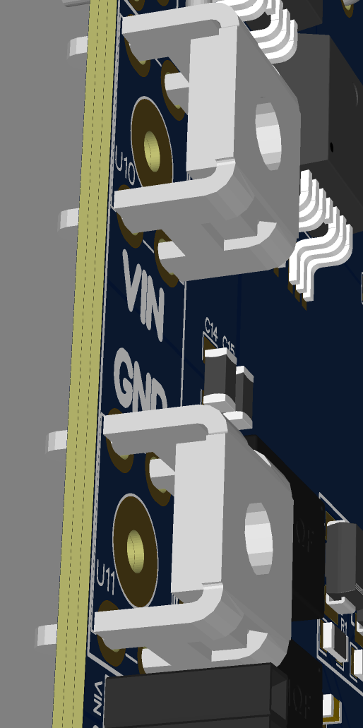
Not true at all. Yes they do. They are called “Cold Pressed Terminals”. You have the choice of SMD or JLC manual solder through hole terminals (but you need to pay extra 3 dollars for a Chinese lady with a soldering iron to get the through holes job done). You will receive the complete board job as if done on the machine. I do manual holes all the time. When I get the time I’ll send you pictures.
Same for the male and female through hole headers. No problem.
Cheers,
Valentine