Which MCU type are you using? Its a new feature for us, implemented on the dev branch and will be part of the next release. So far, we support it on most STM32 MCUs and the RP2040.
You can set it via the build-flag -DSIMPLEFOC_PWM_LOWSIDE_ACTIVE_HIGH=false
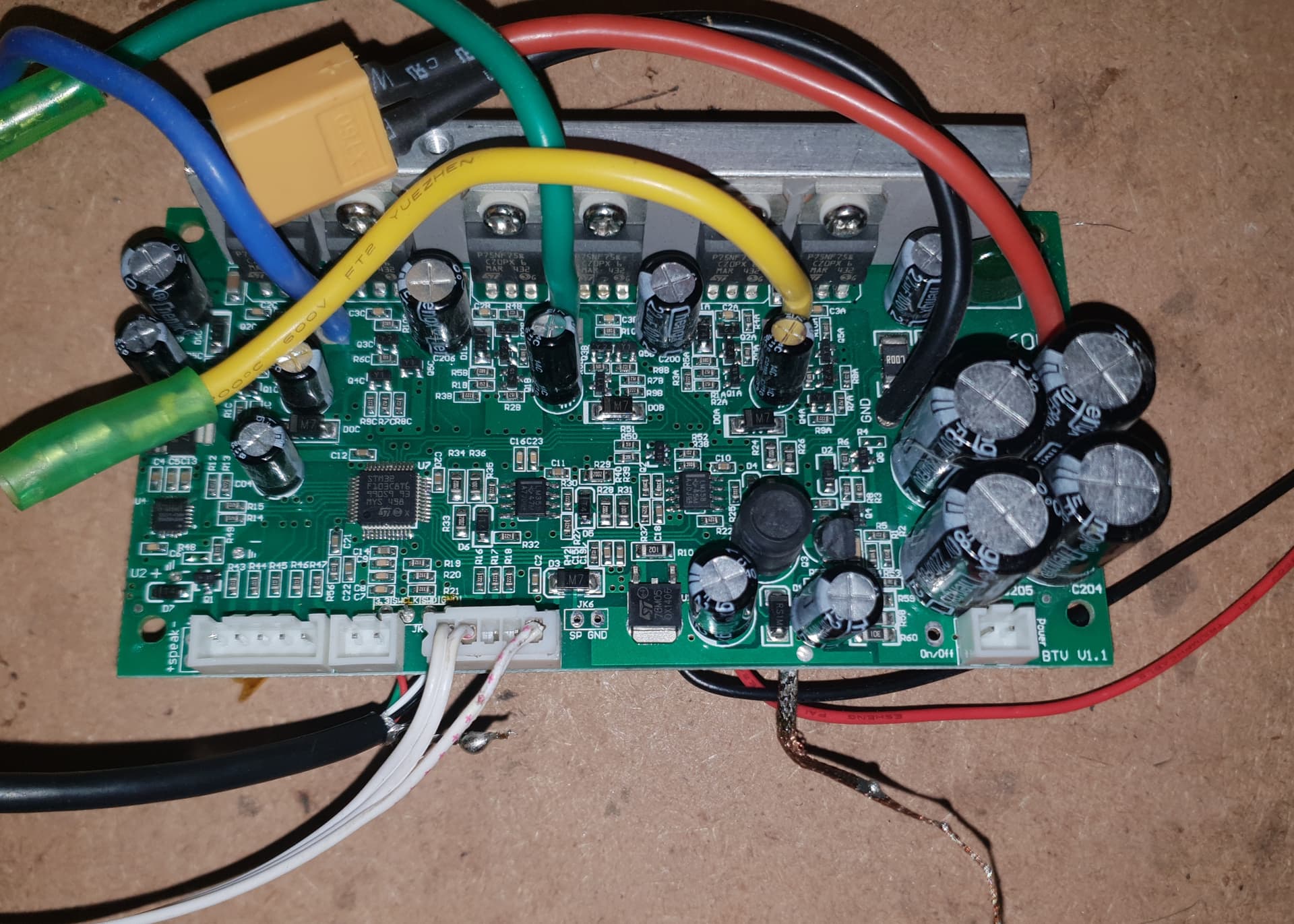
I have a very similar board from a single wheel gyro , using a STM32F103C8T6 and a MPU6050.
I’m puzzled, I don’t know where to start, by the past I was able to play With Feru’github “hoverboard hack” , I also modify some C lines to add extra features.
I’m an electronics with good knowledge in transistor but each time a component got’s more than 3 pins… I’m lost
so yes…
I downloaded library by platformIO “wizard”, and compile exemple for Suresh’s git.
I happy to see a led blinking, at least the tool chain is operationnal.
Now I have to read a little … documentation…
thx, … I though about something like that.
the trick is… MCU is a STM32F103C8T6 , PC isn’t available.
the only free pins that could fit a USUART are for UART3 with PB10 PB11
so I setup Serial3.begin(9600) … but compiler isn’t happy,
I’m dead stupid in C++ and more with arduino…
You probably don’t need to use the HardwareSerial class. Just replace the PC numbers from my previous post with your PB numbers and it should work. Serial, not Serial3.
I generally prefer hardware registers too. I don’t think I’ve ever used a library that didn’t torment me in some way. For example the other day I discovered that Arduino’s implementation of sprintf doesn’t support floating point… I’ve been printing my current values in integer milliamps instead. And it has no way to check if interrupts are currently enabled, even though there are functions noInterrupts() and interrupts() to disable/enable. Obviously you can make wrapper functions that keep track of it, but that’s no good for compatibility with code outside your own library/project.
The STM32 HAL library is one of the worst ever. So much clutter, and makes it more difficult instead of easier. For example my inline current sense ADC setup on G431 would probably be like 5-10 times this much HAL code… and you still have to study how the hardware works, and then study how to get the library to set it the way you want.
before closing the “high power switch” on the board, I checked the power part with my lab PSU, with a current limit. Motor isn’t connected.
For test purpose I used the " BLDC driver standalone example" , with some adaptation …
it was a good idea, immediatly after initialisation was complete, PSU exihitbit a current limit light … saying that “something goes wrong”…
I can see with my scope PWM with a deadtime, so everything is OK with that… unless polarity isn’t the good one…
scratching my head, and starting a small reverse job
guess what.
to activate high side mosfet an high level is required…
but to active low side one, a low level is required.
so , I have exactly the same issue as Suresh
so, I added #define SIMPLEFOC_PWM_LOWSIDE_ACTIVE_HIGH false
at the begining of main.cpp … clean project and rebuild…
… but polarity don’t change!
what’s wrong…
a funny fact … I cannot find reference for SIMPLEFOC_PWM_LOWSIDE_ACTIVE_HIGH elsewhere than hardware_api.h…
strange
All I can say is that it is possible. The hardware register TIM1_CCER has independent polarity selection for each channel (including complementary channels).